JAPANWATCH: Micromechanical cantilever directs waveguides
Incorporating news from O plus E magazine, Tokyo
TOKYOHitachi and Hitachi Cable have used micromachining techniques to develop an optical switch that manipulates optical waveguides with an electromagnet. Many types of optical switches have been developed or have been proposed for communications, depending on the intended function. A micromechanical optical switch could be used as a rerouting switch when obstacles are encountered in a communications path or as a switch to ease the insertion of testing and signal-processing devices.
Operation
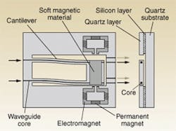
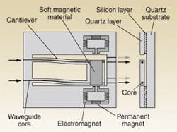
In the newly developed Hitachi switch, two waveguides are created on a cantilevered quartz layer that has a soft magnetic material affixed to one side (see figure). When electricity is applied to an electromagnetic coil, the material on the cantilever becomes magnetic and moves between positions, aligning two of the waveguides on the cantilever with two of the four output waveguides. The waveguides couple as dictated by the position of the cantilever. The coupling space is filled with a liquid with the same refractive index as the waveguides to lessen coupling loss. In this manner, two adjacent 1 x 2 switches can be operated in tandem. A permanent magnet embedded in the electromagnet keeps the parts coupled.
The switch has an insertion loss of 3.1 dB and crosstalk of -40 dB. The operating voltage is 7 V, the current is 350 mA, and the switching speed is 40 ms. The Hitachi researchers have determined that most of the insertion loss stems from shifting the optical axis in the coupling region. Most of the loss is believed to be caused by the accuracy of etching, and the group estimates that continued research can improve performance by reducing insertion loss to 1 dB.
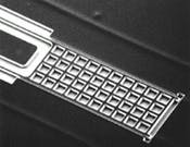
PHOTO. To create a magnetically operated, micromechanical optical switch, a silicon layer is first formed on top of a quartz substrate, and then another layer of quartz is placed above it. Two waveguides are created in the upper quartz layer by dry etching, and the silicon layer is removed by wet etching (top). The resulting upper quartz structure is shaped like a cantilever, to which a soft magnetic material is affixed (bottom).
One of the primary benefits of using electromagnetic switches is that, unlike static-electrically controlled switches, they can be maintained without current. Production is more difficult because of the electromagnetic component, but because this method does not require the high-precision, three-dimensional building capabilities that optical-fiber-manipulation methods require, these switches are better suited for mass production.
Courtesy O plus E magazine, Tokyo


