OPTICS FABRICATION: Ultrasound cleaning technique for laser substrate depends on material
Manufacturing a functional high-power laser optical component requires great care in every step. Even a flawless optical substrate is of no use if it hasn’t been cleaned adequately before thin-film coating. And the cleaning techniques used in the average optical-engineering lab do not apply here.
Researchers at Tongi University and the Shanghai Key Laboratory of Special Artificial Microstructure Materials and Technology (both in Shanghai, China) and the Tianjin Jinhang Institute of Technical Physics (Tianjin, China) are developing ways to clean fused silica and BK7 glass before coating based on better cleaning surfactants combined with ultrasound cleaning.1 The cleaning process affects different substrate materials in different ways.
Two processes
Sample substrates 30 mm in diameter and 5 mm thick were fabricated either of fused silica or BK7. The samples were ground with silicon carbide abrasives, then polished with cerium oxide slurry and pitch pat. Surface contamination was removed by following an ultrasonic-cleaning process that typically had four steps. The details of each step were varied during the experiment to determine the best approach.
First, the substrate was “marinated” in alcohol for at least a hour. Next came ultrasonic cleaning in an aqueous surfactant; the ultrasonic time, power, and frequency were all variables. In the third step, the substrate was rinsed twice in ultrapure water, each time for 5 min, once at 45ºC and once at 65ºC. Finally, the substrate was dried with either hot, clean air or nitrogen for 5 min.
The ultrasonic frequency could be set to 40, 80, 120, or 170 kHz. The diameter distribution of the particles removed from the substrates depended both on the ultrasonic frequency and the solution temperature.
The researchers concentrated on two cleaning processes, process 1 and process 2, each done on the two types of substrates for four total experiments. In process 1, the ultrasonic solution was a commercial alkaline cleaning solution with a chelating detergent containing ionic and nonionic ingredients. For process 2, the scientists mixed their own solution from ammonium hydroxide, hydrogen peroxide, and deionized water, creating a hydrophilic surfaces that helps in particle removal. All experiments were performed under Class 1000 cleanroom conditions.
After cleaning, the absorption of the sample surfaces was nondestructively tested using a surface-thermal-lens technique in which incoming light is locally absorbed, causing small surface deformations that are measured with an atomic-force microscope. The laser-damage threshold of the substrates was measured using a Q-switched Nd:YAG laser at 1064 nm that produced 10 ns TEM00 pulses. The laser beam was focused to a 1/e2 diameter of 1 mm on the substrate. The laser beam was either raster-scanned or scanned in an “R-on-1” pattern across the substrate. In the raster scan, which occurred over a randomly selected 10 mm2 area, the initial dose was 5 J/cm2, which in subsequent scans was then boosted in increments of 5 J/cm2. The R-on-1 measurements tested at least 50 positions on each substrate, with the dose being increased in increments of 0.2 J/cm2 until damage occurred.
Very clean fused silica
After cleaning, the substrates were examined using a darkfield microscope at 45X magnification. For fused-silica surfaces, the darkfield examination showed that although process 1 cleaned all but a few particles in the observed area, process 2 did an even better job, removing nearly all particles in the area (0–5 particles remaining in a 1 mm2 area). For BK7, the solutions did not perform quite as well, leaving 10–20 particles in a 1 mm2 area for process 2.
Fused-silica surface roughness increased slightly upon cleaning in both processes, as did roughness of BK7 after process 1. However, the BK7 surface roughness changed substantially (from 0.662 to 2.244 nm) when cleaned via process 2. This is likely due to the lower chemical stability of BK7 glass, say the researchers.
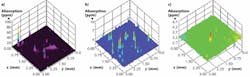
A surface-thermal-lens measurement of the samples revealed their thermal-absorption characteristics (see figure). For fused silica, the average absorption after cleaning with process 2 was about 4.5 ppm/mm. For BK7, the average absorption was around 5200 ppm/mm, due to its increased surface roughness.
Laser-damage-threshold tests were not conclusive, showing only slightly better performance for process 2 versus process 1 for fused silica (85 versus 80 J/cm2 for the R-on-1 scan). The researchers felt that in their experiment, laser damage due to remaining particles could not be adequately separated from laser damage due to surface and subsurface defects created during grinding and polishing.
The team believes that the results of their tests (showing that process 2 is better for fused silica) could be relevant for other choices of abrasives and polishes used to fabricate fused-silica laser optics. They are also in the process of improving wet-chemical cleaning methods to optimize laser-damage thresholds for BK7.
REFERENCE
1. Z. Shen et al., Appl. Opt., 50, 9, C433 (Mar. 20, 2011).
About the Author

John Wallace
Senior Technical Editor (1998-2022)
John Wallace was with Laser Focus World for nearly 25 years, retiring in late June 2022. He obtained a bachelor's degree in mechanical engineering and physics at Rutgers University and a master's in optical engineering at the University of Rochester. Before becoming an editor, John worked as an engineer at RCA, Exxon, Eastman Kodak, and GCA Corporation.