Quick tutorial: Laser beam profiling with camera-based systems
The shape, size, and features of your laser beam are important factors to determine the effect a laser beam will have when it is eventually absorbed. Small changes in size can greatly affect power density. Contamination in optics can produce distortions. Errors in assembly procedures or changes over time can affect the beam as well. Laser beam profiling will verify that all the links in your optical chain are functioning properly.
Measuring a beam profile with a CMOS sensor
Depending on your application, you may want a beam with no astigmatism or a large astigmatism. You may want a Gaussian beam shape, or top hat, or a more complicated beam pattern. The focal point of your laser may shift over time and with environmental changes.
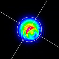
Camera-based laser beam profilers are a low-cost and simple way to view a slice of your laser. By placing the camera in the optical path, the relative intensity of each location in the beam is digitized and recorded. The profile, or slice, of your laser beam at this position can then be displayed and analyzed using the camera PC software (see Fig. 1).
CMOS camera sensors are built out of millions of individual elements that together capture the entire laser beam, producing an image of the profile. CMOS sensors in laser beam profilers are very similar to sensors found in smartphones and digital cameras, but are specially manufactured for laser beam profiling. CMOS profilers typically can be used for lasers with wavelengths from 350 to 1150 nm; these wavelengths can be extended by additional adapters.
Selecting sensor and pixel size
Properties of CMOS sensors determine the maximum and minimum size of the laser beam that can be profiled. The property that determines the minimum beam size is the pixel pitch or distance between each individual element in the sensor. It is recommended that a minimum of 10 pixels be illuminated by your laser. If the pixel pitch in the camera datasheet is 5.5 μm, the minimum laser beam diameter should be 55 μm.
The property that determines the maximum beam size is the sensor area. Some sensors are quite small, only a few millimeters wide; and many sensors are not square, but rectangular. Not only will this limit the maximum laser beam size, but it can make it quite difficult to align your laser.
Setting up the profiler
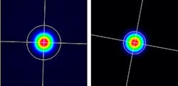
Several camera settings can be adjusted to acquire a good quality profile of the laser, such as exposure time (shutter time) and gain. Usually, the software will adjust these parameters automatically, if you perform a background subtraction. Performing a background subtraction lets the camera know what the ambient light looks like so it can ignore it and show you only the laser beam profile. This procedure will involve blocking the laser, taking an image, then unblocking the laser (see Fig. 2); it is explained in detail in this video.Measuring the beam profile
Once the camera is installed and the laser aligned, an image of the profile can be taken. This image is transferred to the PC software for analysis (see Fig. 3). In Gentec-EO’s software, the image can be viewed in 2D or 3D, with the relative intensity of each pixel representing height in the vertical axis. The software will also show the X and Y coordinates of the beam center on the sensor; the beam diameter, and X and Y diameters if there is astigmatism; and other more advanced types of measurements. Since there are several different ways to calculate beam diameter, a few different options are offered.Include beam profiling in production
When scaling up from the lab to the production floor, ensuring beam quality at multiple points in your assembly and configuration processes can help save time and reduce headaches. Integrating beam profilers into your production procedures can catch problems early on, turning big problems into smaller ones. Laser beam profiling cameras can also be interfaced with automation software.
In a modern production environment, being able to verify laser beam quality, and to have a stored proof of beam quality in your production archives, can aid in highly technical assembly processes and in post-sales service and support tasks. Knowing exactly what your beam is doing at several different points in experiment, design, and production can help you produce reliable and consistent results.
About the Author
Nicholas Prefontaine
Product Manager, Gentec-EO
Nicholas Prefontaine is a product manager at Gentec Electro-Optics (Gentec-EO; Quebec City, QC, Canada).


