The metrology story behind the James Webb Space Telescope
The James Webb Space Telescope (JWST) is now undergoing final deployment in space. It will operate at a nominal temperature of under 50K (-350°F), under a high vacuum of deep space 1.5 million kilometers from Earth—well beyond any possible manned service missions.1 The telescope uses technologies such as a primary mirror that comprises meter-class segmented lightweight beryllium mirrors; actuators for aligning and shaping the segments; and a carbon fiber backplane structure.
Modeling of the system was necessary for design but wasn’t adequate to ensure performance, particularly with the high cost of deployment and its inability to be serviced once deployed. Testing of the optics and structures was particularly challenging because of their large physical size and creating space-like conditions on Earth requires vacuum chambers with cryo-cooling, which involves mechanical pumps that induce significant vibration and makes precise optical measurements difficult.
While JWST was being designed and early proof-of-principle experiments were being conducted, commercial single-shot dynamic interferometry instruments were also in development. The JWST program adopted this technology and the unique needs of the program accelerated product development within this area.
Several of JWST’s metrology needs were addressed with dynamic interferometry:
- Primary segment figure during fabrication at ambient and cryo-vacuum conditions
- Secondary convex mirror figure under cryo-vacuum conditions
- Thermal stability of the carbon fiber backplane structure
- Vibrational stability and survivability of the segments
- Verification of segment phasing and full-up telescope wavefront
Dynamic interferometry methods and configurations
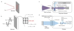
Phase-shifting interferometry is a well-established method for measuring optical wavefront phase to a few nanometers or better. But any relative motion between frames caused by vibration introduces an error and may preclude measurement altogether.2 Several different methods have emerged during the last several decades for snap-shot interferometry, offering significant vibration immunity as well as the ability to measure dynamic events. Two of the main methods are shown in Figure 1. The spatial carrier method (see Fig. 1a) is compact and requires only a known angle to be introduced between the reference and test beams. But it has a significant practical drawback: the beams travel along different paths through the imaging and/or illumination system and may be sheared at the detector. This prohibits the use of broadband light sources and introduces a variable systematic error that must be measured and accounted for to properly calibrate the system for every use case (for example, small changes to the instrument focus may alter residual errors).
To address the needs of JWST, 4D Technology developed a compact approach that uses polarization to encode the reference and test beams (see Fig. 1b).3 This technique uses a micro-polarizer array to induce a relative phase between reference and test beams on a pixel-by-pixel basis. A single exposure acquires a multiplexed interferogram without the need for tilt between the beams. Broadband light sources (both spectral and spatial) can be used, and illumination and imaging can be done on-axis. This approach is sensitive to polarization aberrations within the optical measurement path, but can be calibrated without the need for artifacts or multiple alignments.4 The Twyman-green (TG) and Fizeau interferometers, which use this sensor, are shown in Figure 1c and 1d, respectively.
Concave primary mirrors
The heart of the telescope (see Fig. 2) is its primary mirror, which provides the large light gathering cross section. It consists of 18 meter-class beryllium mirror segments that required testing in ambient conditions to provide feedback for polishing, as well as under cryo-vacuum conditions to verify its expected final shape. The segments were tested by aligning the interferometer beam focus to the 16-meter center of curvature (see Fig. 2a). A computer-generated hologram was used to compensate for the aspheric departure of the elements, and several varieties of dynamic TG interferometers were created to measure the individual segments and the full-up array. The TG configuration can accommodate a large range of test path throughputs, produce high light collection efficiency to minimize exposure time and optimize vibration immunity, and result in on-axis illumination and imaging, which avoids the systemic errors associated with spatial carrier methods.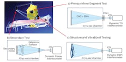
Convex secondary mirrors
Measurement of the convex secondary mirror is considerably more challenging than concave mirrors, because they must produce converging light over a large aperture. The Fizeau configuration (see Fig. 2b) is a preferred configuration, with its main advantage of common path arrangement. This is also the main challenge for implementing a dynamic Fizeau interferometer because it proves difficult to separate the reference and test beams and maintain on-axis illumination and imaging.
To meet the need for an on-axis dynamic Fizeau system, an instrument using a source module made of a broadband, low-temporal coherence laser source was developed, along with an optical delay line that introduces a controllable delay between two orthogonally polarized components of the source.5 The specialized polarization source is injected into a Fizeau interferometer that includes a micro-polarizer phase sensor. By matching the source module optical delay line to the external Fizeau optical path, beams from the reference and test surfaces will be temporally coherent with each other and have orthogonal polarizations. This is required for the snap-shot phase sensor and results in an on-axis, single-shot, vibration-insensitive Fizeau interferometer. Along with the benefits of on-axis operation and vibration insensitivity, use of a tunable delay line allows specific surfaces within the measurement cavity to be isolated for interference. Surface isolation makes remote cavity measurements, such as the configuration required for the secondary mirror, or thin parallel plates, possible.
On-axis, dynamic Fizeau was used to test the secondary optic within the cryo-vacuum chamber at NASA’s flight center, and to verify the performance under simulated space conditions.6
Structure stability
It was imperative to measure the stability of the backplane structure, on which the mirrors are mounted, over the cryo-temperature operational range, but it presented several challenges. It’s constructed of a black carbon fiber material, which is optically diffuse, so only a very small portion of incident light is reflected to the imaging system and the image is dominated by laser speckle noise. The diffuse reflection precluded direct interferometric measurement of the surface shape; however, the change in structure shape can be accurately measured using electronic speckle pattern interferometry (ESPI).2 ESPI measures the change in shape of the rough surface by subtracting a baseline phase measurement from future measurements. The phase-subtraction removes the random speckle intensity pattern and allows measurement of the underlying shape change.
The dynamic ESPI developed for measuring JWST’s backplane uses a TG configuration and a high-energy pulsed laser to obtain sufficient reflected light and freeze any vibrational motion.7 The interferometer measured 3-meter-diameter carbon fiber structures at a 16-meter standoff. This system has an RMS repeatability of 2.1 nm and was used to verify the mechanical models of JWST’s backplane.8 Figure 3 shows the dynamic ESPI interferometer, the JWST backplane sample, and a cumulative 24-hour thermal cycle measurement with positional stability of 23 nm/K—well under the design budget of 100 nm/K.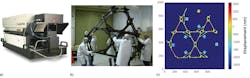
Vibrational measurements
Measuring vibrational-induced strain ensures the structures and mirrors will retain their shape after the harsh environmental conditions during launch, and confirms the deployed structure is well damped for crisp imaging during long exposures. A series of tests were performed using both the ESPI system, where segments were measured before and after acoustic shock, and a second high-speed dynamic interferometer to characterize the stability of JWST’s optomechanical systems.9 The interferometer captured measurements at a rate up to 5000 fps.
One of the mounted JWST primary mirror segments was mechanically excited during testing, and the segment shape, piston, and tilt with the high-speed dynamic interferometer were synchronously measured. The motions of the segment were tracked by temporally unwrapping the measured phase and calculating a pixel-wise power spectrum of the motion in time. Analysis of the results indicate a subnanometer level of surface motion, which is within specified tolerance. Figure 4 depicts the high-speed interferometer measuring the JWST segment at NASA’s Goddard Space Flight Center.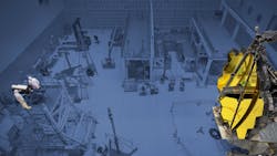
Full array and segmented mirror phasing
Segmented mirrors pose an additional measurement challenge because the segments need to be placed in the appropriate z-plane relative to one another to within nanometers. The primary mechanism to phase the segments in flight relies on iterative analysis of images, but independent verification was required during ground testing. While interferometry has extremely high vertical resolution, it also has a small dynamic range for measuring step discontinuities—requiring less than one-quarter of the measurement laser wavelength, about 150 nm, to be unambiguously resolved.
The dynamic range of an interferometric measurement can be extended through two-wavelength interferometry, where two measurements are captured at different wavelengths of light and subtracted.10 The resulting difference represents a measurement taken at a much longer synthetic wavelength: λs = λ2/Δλ, where Δλ is the difference in laser wavelength. The two-wavelength approach was combined with the dynamic TG configuration, using a combination of two fixed lasers with a tunable laser to generate synthetic wavelengths ranging from 10 mm down to 18 µm. The mirror segments were phased by an iterative process starting at the longest synthetic wavelength and progressively stepping to lower synthetic wavelengths. Measurements at a 16.7 µm synthetic wavelength and the fundamental wavelength at 687 nm agreed to within 13 nm. Data was measured at NASA’s Johnson Space Flight Center, where the two-wavelength interferometer was used to verify proper phasing of segments and the overall wavefront performance of the full primary mirror (see Fig. 5).11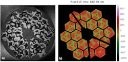
Dynamic Interferometry has and will continue to play a major role in the production of state-of-the-art optical instruments, as well other precision manufacturing applications in semiconductor, aerospace, and life sciences, achieving subnanometer resolution over vibrational timescales of microseconds to thermal timescales of days.
ACKNOWLEDGMENT
The authors would like to acknowledge the amazing work by scientists at NASA, the University of Alabama Huntsville, Ball Aerospace, Coherent (formerly Tinsley), L3-Harris (formerly Kodak, Excellis), and Northrop Grumman.
REFERENCES
1. See www.jwst.nasa.gov.
2. D. Malacara, M. Servin, and Z. Malacara, “Interferogram analysis for optical testing,” Marcel Dekker, New York (1998).
3. J. E. Millerd et al., Proc. SPIE, 5531, 304–314 (2004).
4. B. Kimbrough, N. J. Brock, and J. E. Millerd, Proc. SPIE, 8126, 81260H (2011). ·
5. B. Kimbrough, J. Millerd, J. Wyant, and J. Hayes, Proc. SPIE, 6292 (2006).
6. K. Z. Smith and T. C. Towell, Proc. SPIE, 8126, 81260O (Sep. 27, 2011).
7. M. B. North-Morris, J. E. Millerd, N. J. Brock, J. B. Hayes, and B. Saif, Proc. SPIE, 5869, 337-3459 (2005).
8. B. Saif et al., Appl. Opt., 47, 737–745 (2008).
9. B. Saif et al., Appl. Opt., 54, 4285–4298 (2015).
10. Y. Y. Cheng and J. C. Wyant, Appl. Opt., 23, 4539–4543 (1984).
11. J. Hadaway et al., Proc. SPIE, 10698, 1069803 (2018).
About the Author
James E. Millerd
Technical Consultant, 4D Technology
James E. Millerd is a technical consultant at 4D Technology (Tucson, AZ).
Neal Brock
Technology Consultant, 4D Technology
Neal Brock is a technology consultant at 4D Technology (Tucson, AZ).
Michael North-Morris
Senior Director of Product Development, 4D Technology
Michael North-Morris is senior director of product development at 4D Technology (Tucson, AZ).