Synchronization choices are key to accurate PIC component characterization
The extensive use of photonic integrated circuits (PICs) driven by advanced networking technologies has significant implications for testing the key components that underpin today’s datacenter and telecom networks. The 2020 telecom world sees proliferation of 5G globally, an increase in network and datacenter rates to 800G, greater bandwidth and energy efficiency requirements for high-speed networks, and ongoing and escalating demand for compact, connected devices and integrated optics. Component vendors need faster and more-reliable test methods than ever before to keep pace with this burgeoning demand and to accommodate new optical component characteristics.
This article delves into future-proof testing techniques, addressing the ever-evolving and tighter testing requirements of PICs. The most popular setups use an optical source combined with an optical spectrum analyzer. Other setups use one or more tunable laser sources combined with one or more optical power meters. Regardless, both setups require synchronization between the source and receiver, making the choice between electrical or optical synchronization a key to success.
Economical broadband test solution
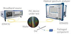
When measuring only insertion loss as a function of wavelength on a single-channel device, a broadband source and optical spectrum analyzer (OSA) setup typically provides a lower-cost testing solution for passive optical components when compared to systems based on a tunable laser and optical power meter(s). However, when contemplating a broadband and OSA setup, several factors should be considered: the broadband source should cover a wider optical spectrum than the PIC under test; it should have a flat optical spectrum; and it should have stable optical power.
With no wavelength synchronization required between the two instruments other than the need to make a reference measurement without the PIC under test, a broadband source and OSA setup has an advantage. Stored in OSA memory, this reference trace gets subtracted from the measurement of the PIC under test. The result is a graph representing the insertion loss vs. wavelength.
When combined with the chip, the light can be collected and coupled to the OSA, which will then perform a sweep to record the spectral response of the PIC device under test (see Fig. 1). The speed of this method makes it suitable for real-time alignment; however, there are limitations to its scope. Given that a PIC is often high contrast, the OSA method does not always provide the optimum solution. A second parameter to take into consideration is that the resulting optical spectrum is always a convolution of the actual PIC-under-test signal and the OSA’s monochromator’s response, leading to spectral errors when measuring very sharp spectral features.
For example, EXFO’s OSA20 has a fixed optical bandwidth of 20 pm, which allows for passive component testing at a resolution of 200 pm and greater to be measured with very little error. However, a PIC with sharper features (typically 20 pm or less) will incur greater inaccuracy in spectral shape. In the latter case, a higher-resolution setup would be required, consisting of a high-resolution tunable laser with optical power meter setup.
Therefore, a broadband source and OSA setup provides a cost-effective solution for testing low-loss, single-channel passive components on insertion loss only, such as the example of the OSA20 not requiring a resolution less than 20 pm.
In addition, this setup can be complemented by a remote-control computer coupled to a wafer disc handler for an automated PIC wafer disc test solution. Having an OSA as part of this setup enables characterization of active PIC devices such as laser diodes and LEDs.
Economical high dynamic range broadband test solution
The optical power provided by a broadband source might be high enough for PIC testing, but equally important is the noise floor (spontaneous source emission, or SSE) of the source. The combination of the two determines the dynamic range of the source, which translates into the actual usable dynamic range to test the device. A broadband source provides a dynamic range on the order of 30 to 50 dB, whereas a tunable laser typically provides a dynamic range between 50 and 90 dB.
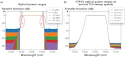
An alternative to the broadband + OSA setup above is to use a step-type tunable laser source (TLS) + OSA, which is effective when a high dynamic range is needed, such as when characterizing higher loss or cascaded PICs on insertion loss vs. wavelength (see Fig. 2).
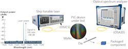
As in a broadband source setup, the TLS + OSA setup does not require synchronization of any sort between the source and OSA. A step TLS + OSA makes a flexible test setup for those applications in which only one wavelength at the time needs to be tested. Upon completion of the test at a given wavelength, a new active TLS wavelength can be selected after which a new measurement with the OSA can be taken.
Even though a simultaneously sweeping laser with OSA would provide results faster, in this setup a step type tunable laser source is preferred over a swept-type TLS. A swept-type TLS with OSA would require highly accurately timed electrical synchronization between the TLS and OSA, which is frequently not straightforward, primarily because of four variables: 1) the acceleration and deceleration time of the TLS combined with its selected sweeping speed; 2) response time behavior of the PIC under test; 3) the acceleration, deceleration time, and sweep speed of the OSA; and 4) the speed of the electrical synchronization bus between the TLS and OSA.
The electrical synchronization in this setup would represent timing synchronization between the TLS and OSA and not wavelength. Some tunable laser sources facilitate a wavelength-sensitive electrical output and provide an electrical pulse train while sweeping, eliminating the need for an external PC in which case no programming is needed.
However, the accuracy of direct wavelength synchronization is subject to the optical performance of the tunable laser (i.e., mode hops) and the quality of the high-speed electronic circuitry supporting the SYNC bus. By using the wavelength accuracy of the OSA as the point of reference, enabled by establishing an absolute wavelength reference that can be made by using a built-in or optional acetylene gas cell for self-calibration, rules out any possible electrical wavelength synchronization issues.
Ultimately, a step-type TLS + OSA setup provides a higher dynamic test solution, but in terms of resolution is subject to the same parameters as a broadband + OSA setup. It is limited to testing single-channel passive optical components on insertion loss vs. wavelength only, with the advantage that an OSA in this setup enables active component testing as well.
Full-spectrum characterization of high-resolution and high-dynamic-range passive PICs while limiting any variables that can cause errors requires a more elaborate system consisting of a swept-type tunable laser source with one or more optical detectors.
Swept-laser testing for advanced PIC reliability
PICs are evolving at a very rapid pace, making designs more and more complex. This evolution, coupled with the ever-increasing bandwidth demands of telecom and datacom networks, is driving the need for accurate, reliable, and fast test solutions that are not just limited to insertion loss vs. wavelength characterization. The common test parameters of high-speed PICs are typically insertion loss (IL), polarization depended loss (PDL), and return loss (RL) as a function of wavelength, measured at a picometer resolution. PIC devices ranging from 1 × 1 ports to 64 × 64 ports and higher require a different setup from a broadband or tunable laser and OSA.
These requirements set the bar high and demand confirmation of the exact wavelength while measuring high dynamic range and high optical resolution. Ultraresponsive optical detectors with low noise output are a must for ring-resonator characterization. They must also have multiport capability, with scalable and repeatable measurement results.
The only test approach that is proving to lead the pack when it comes to delivering fast and reliable measurements for today’s complex components is the swept-laser technique. This elegant solution uses a continuously tunable laser source along with a component tester that records wavelength and power detection synchronously as the wavelength is scanned by the laser. Within seconds, it can deliver picometer spectral resolution with a very large optical power dynamic range. It also does not experience convolution error found in the OSA + broadband source-based measurement.
In case of a mismatch, test results would vary depending on which auto-ranging stage the measurement was taken, representing itself as a glitch in the PIC’s spectral response. The exclamation marks in Figure 5a show the anomaly at both sides of a PIC measured at different dynamic range settings. Situations like these require multiple scans, adding to the overall measurement time to characterize the PIC. Single-scan “one dynamic range” optical detectors rule out any variables, representing the optical characteristics of the PIC under test only (see Fig. 5b).
Future-ready multichannel swept-type optical component testing
Quality component testers combine multiple lasers to cover the full range of optical components. The larger spectral range, important when characterizing components spanning all telecom bands, can be tested using several tunable lasers—each of which covers a portion of the total spectrum under test—and concatenating the insertion loss or return loss result into a single spectrum.
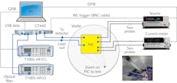
To match the high quality of the laser, the component tester must be leading-edge, providing very short test times and excellent accuracy to record the test wavelength and output power simultaneously as the laser is being swept. This synchronized measurement is performed automatically by the component tester. The component tester can also be automated to allow, for example, “fixed wavelength” power measurement, which is crucial for the fast fiber-to-PIC alignment algorithm.
The synchronization between the tunable laser source(s) and optical power meters is one of the most critical aspects of the system. Behavior of latest PIC designs have proven very wavelength dependent and may respond very differently. Just a few picometers apart could make the difference between a component pass or fail. This calls for perfect wavelength synchronization, achievable optically using a known reference.
One technique to achieve such picometer resolution is to use electronic triggers provided by the tunable laser to read optical power on each output detector. However, this requires high-precision tunable laser electronics and is often laser sweep speed-dependent, directly translating into limitations on spectral quality of measurement of the PIC under test.
In contrast, both EXFO’s CT440 and CTP10 facilitate optical synchronization between the sweeping tunable laser source and a known wavelength reference, addressed by the built-in all-optical wavelength referencing engine against which the incoming signal is being compared. This in turn is used to synchronize the source and optical detectors.
This engine, implemented in EXFO’s CTP10 and CT440, guarantees a wavelength accuracy of ±5 pm with excellent repeatability on the order of 1 pm transparent from the laser scanning speed, which can be further improved on by adding an external acetylene gas cell (see Fig. 6).
The optical characteristics of this all-optical engine do not experience the limitations of an electrical synchronization connection between source and receiver, enabling other applications beyond spectral testing. This would include, for example, heterodyning of active signals or optical frequency-domain reflectometry (OFDR), allowing for troubleshooting PIC components at a micrometer resolution.
Looking forward
Reliance on PIC technology is increasing as network transformations continue globally. Clearly, future-proof PIC testing solutions are an integral part of that evolution, addressing speed, accuracy, and reliability in component manufacturing. Further information on this topic is available here.
Having discussed the most popular setups and choices between electrical and optical synchronization in this piece, a subsequent article will address scalable, future-proof PIC testing solutions highlighting EXFO’s collaboration with Hewlett Packard Enterprise (HPE) and MPI. For a preview, visit EXFO’s blog.
About the Author

Lawrence van der Vegt
Lawrence van der Vegt is the head of photonics at MPI Corp. He is an optics veteran; he earned his bachelor's degree in electrical and computer engineering at De Blauwe Kei College (Netherlands) and has held various key directorial positions at optical test and measurement companies in The Netherlands and the U.S.