CREATE MORE EFFICIENT OPTICAL DESIGNS WITH INTENTIONAL VIGNETTING AND CONTRAST LOSS MAPPING

With the demand for thinner and lighter lenses for everything from cell phones to lidar to virtual reality headsets, there can be a reliance on onboard software as a safety net to “fix” faulty optical systems. But optical designers need to take the entire system into account during the design process to achieve the best, most cost-effective product in the most efficient way possible. Vignetting and contrast loss are two distortions that onboard software often corrects for and should be understood during the design process by engineers.

Designing optical systems with intentional vignetting
Vignetting factors are a powerful tool in lens design that are underused today. In a vignetted system, apertures trim the optical beam at wide field angles. This typically causes the final image to be darker at the corners than at the center, which is undesirable. But it also improves the quality of the image in the central regions by trimming away some of the aberrations in the beam. This allows for optical designers to avoid overdesigning their systems—and create designs that use fewer or simpler lenses than a comparable system without vignetting.
Vignetting factors allow optical designers to specify a smaller beam in the entrance pupil of the system, even before they’ve gotten the apertures and number of lenses worked out. Software can help. For example, vignetting can be modeled in OpticStudio manually and automatically using five scale factors: VCX, VCY, VDX, VDY, and VAN.
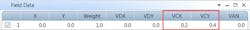
These vignetting factors allow the user to modify the size, shape, and orientation of the beam in the entrance pupil as seen by any field point in the system. Rays are then launched from each field point to uniformly illuminate the modified pupil. Without vignetting factors, systems correct the aberrations for the full-size beam over the entire field of view of the system. The result is a lens system that is overcorrected.
The importance of mapping contrast loss
Understanding how contrast is lost or varies in an optical system is another critical piece of the design puzzle in creating smaller and lighter lenses and optical design software can help. For example, the Contrast Loss Map feature in OpticStudio provides an easy way to understand how contrast varies or is lost in an optical system. It visualizes contrast loss for a specific frequency of the Modulation Transfer Function (MTF) as a distribution map across the exit pupil.
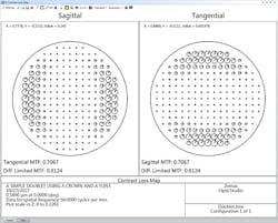
Contrast Loss Map gives insight into how the MTF is degrading across the pupil. Users can then use the data to determine what changes to make to their system to improve MTF. Contrast Loss Map plots the same contrast loss values that are calculated during Contrast Optimization, which uses the Moore-Elliott method to optimize for MTF up to 30 times faster than traditional methods, helping optical designers get to a high-confidence design faster.

Contrast Loss Map gives insight into how the MTF is degrading across the pupil, helping to optimize for MTF up to 30 times faster than traditional methods.