An Introduction to Polarization
Understanding and manipulating the polarization of light is crucial for many optical applications. Optical design frequently focuses on the wavelength and intensity of light, while neglecting its polarization. Polarization, however, is an important property of light that affects even those optical systems that do not explicitly measure it. The polarization of light affects the focus of laser beams, influences the cut-off wavelengths of filters, and can be important to prevent unwanted back reflections. It is essential for many metrology applications such as stress analysis in glass or plastic, pharmaceutical ingredient analysis, and biological microscopy. Different polarizations of light can also be absorbed to different degrees by materials, an essential property for LCD screens, 3D movies, and your glare-reducing sunglasses.
Understanding polarization
Light is an electromagnetic wave, and the electric field of this wave oscillates perpendicularly to the direction of propagation. Light is called unpolarized if the direction of this electric field fluctuates randomly in time. Many common light sources such as sunlight, halogen lighting, LED spotlights, and incandescent bulbs produce unpolarized light. If the direction of the electric field of light is well defined, it is called polarized light. The most common source of polarized light is a laser.
Depending on how the electric field is oriented, we classify polarized light into three types of polarizations:
- Linear polarization: the electric field of light is confined to a single plane along the direction of propagation. (Figure 1)
- Circular polarization: the electric field of light consists of two linear components that are perpendicular to each other, equal in amplitude, but have a phase difference of π/2. The resulting electric field rotates in a circle around the direction of propagation and, depending on the rotation direction, is called left- or right-hand circularly polarized light. (Figure 2)
- Elliptical polarization: the electric field of light describes an ellipse. This results from the combination of two linear components with differing amplitudes and/or a phase difference that is not π/2. This is the most general description of polarized light, and circular and linear polarized light can be viewed as special cases of elliptically polarized light. (Figure 3)
Figure 1: The electric field of linearly polarized light is confined to a single plane along the direction of propagation.
Figure 2: The electric field of circularly polarized light consists of two perpendicular, equal in amplitude, linear components that have a phase of difference of π/2. The resulting electric field describes a circle.
Figure 3: The electric field of elliptically polarized light consists of two perpendicular linear components with any amplitude and any phase difference. The resulting electric field describes an ellipse.
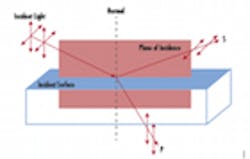
The two orthogonal linear polarization states that are most important for reflection and transmission are referred to as p- and s-polarization. P-polarized (from the German parallel) light has an electric field polarized parallel to the plane of incidence, while s-polarized (from the German senkrecht) light is perpendicular to this plane.
Figure 4: P and S are linear polarizations defined by their relative orientation to the plane of incidence.
Manipulating polarization
Polarizers
In order to select a specific polarization of light, polarizers are used. Polarizers can be broadly divided into reflective, dichroic, and birefringent polarizers. More detailed information on which type of polarizer is right for your application can be found in our Polarizer Selection Guide.
Reflective polarizers transmit the desired polarization while reflecting the rest. Wire grid polarizers are a common example of this, consisting of many thin wires arranged parallel to each other. Light that is polarized along these wires is reflected, while light that is polarized perpendicular to these wires is transmitted. Other reflective polarizers use Brewster’s angle. Brewster’s angle is a specific angle of incidence under which only s-polarized light is reflected. The reflected beam is s-polarized and the transmitted beam becomes partially p-polarized.
Dichroic polarizers absorb a specific polarization of light, transmitting the rest; modern nanoparticle polarizers are dichroic polarizers.
Birefringent polarizers rely on the dependence of the refractive index on the polarization of light. Different polarizations will refract at different angles and this can be used to select certain polarizations of light.
Unpolarized light can be considered a rapidly varying random combination of p- and s-polarized light. An ideal linear polarizer will only transmit one of the two linear polarizations, reducing the initial unpolarized intensity I0 by half,
For linearly polarized light with intensity I0, the intensity transmitted through an ideal polarizer, I, can be described by Malus’ law,
Where θ is the angle between the incident linear polarization and the polarization axis. We see that for parallel axes, 100% transmission is achieved, while for 90° axes, also known as crossed polarizers, there is 0% transmission. In real world applications the transmission never reaches exactly 0%, therefore, polarizers are characterized by an extinction ratio, which can be used to determine the actual transmission through two crossed polarizers.
Waveplates
While polarizers select certain polarizations of light, discarding the other polarizations, ideal waveplates modify existing polarizations without attenuating, deviating, or displacing the beam. They do this by retarding (or delaying) one component of polarization with respect to its orthogonal component. To help you determine which waveplate is best for your application, read Understanding Waveplates. Correctly chosen waveplates can convert any polarization state into a new polarization state, and are most often used to rotate linear polarization, to convert linearly polarized light to circularly polarized light or vice versa.
Applications
Implementing polarization control can be useful in imaging applications. By placing a linear polarizer over the light source, the lens, or both, it is possible to eliminate glare and hot spots from reflective objects or bring out surface defects.
Figure 5: To learn more about using polarizers to reduce glare, read Successful Light Polarization Techniques.
Material stress can be quantified in transparent objects using the photoelastic effect. Stressed material becomes birefringent, and the stress and its related birefringence can be measured by using polarized light.
Figure 6: For more information on using polarization to measure stress, read Successful Light Polarization Techniques or Contact Us.
Polarization is also very important in the chemical, pharmaceutical, and food and beverage industries. Many important chemical compounds, such as active pharmaceutical ingredients or sugar, are “optically active” and rotate polarized light. The amount of rotation is determined by the nature and the concentration of the compound, allowing polarimetry to detect and quantify these compounds.
About Sponsor
Edmund Optics is a leading supplier of optics and optical components, designing and manufacturing a wide array of multi-element lenses, lens coatings, imaging systems, and opto-mechanical equipment. EO’s state of the art manufacturing capabilities combined with its global distribution network has earned it the position of the world’s largest supplier of off-the-shelf optical components. Customers can purchase items by calling 1-800-363-1992, via the catalog or the website at http://www.edmundoptics.com/