Introduction to Optical Coatings
An optical coating is composed of a combination of thin film layers that create interference effects used to enhance transmission or reflection properties within an optical system. The performance of an optical coating is dependent upon the number of layers, the thickness of the individual layers and the refractive index difference at the layer interfaces. The most common types of coatings used on precision optics are: Anti-Reflection (AR) Coatings, High Reflective (Mirror) Coatings, Beamsplitter coatings, and Filter coatings. Anti-reflection coatings are included on most refractive optics and are used to maximize throughput and reduce ghosting. High Reflective coatings are designed to maximize reflectance at either a single wavelength or across a broad range of wavelengths. Beamsplitter coatings are used to divide incident light into known transmitted and reflected light outputs. Filters are found in a large number of industry applications and are used to transmit, reflect, absorb, or attenuate light at specific wavelengths. Edmund Optics can also offer a variety of Custom Coatings to meet any application need.
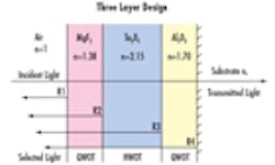
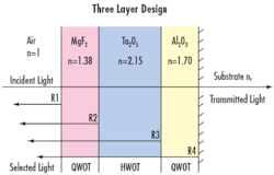
Figure 1: Sample Three Layer BBAR Coating Design
Optical Coatings are designed for a specific incident angle of light and for a specific polarization of light such as S-polarized, P-polarized, or random polarization. If a coating is designed for light at a 0° angle of incidence, but is used with light at a 45° angle of incidence, the coating will not perform at the stated transmission/reflection specifications. Similarly, coatings are generally designed for randomly polarized light so using S-polarized or P-polarized light with a coating designed for randomly polarized light will again fail to produce the stated specifications.
Optical Coatings are created by depositing dielectric and metallic materials such Ta2O5 and/or Al2O3 in thin layers that are typically quarter-wave optical thickness (QWOT) or halfwave optical thickness (HWOT) the wavelength of the light used in the application. These thin films alternate between layers of high index of refraction, and low index of refraction, thereby inducing the interference effects needed. Refer to Figure 1 for a sample illustration of a broadband anti-reflection coating design.
Coatings control the reflection and transmission of light through the mechanism of optical interference. When two beams propagate along coincident paths and their phases match, the spatial location of the wave peaks also match and will combine to create a larger total amplitude. When the beams are out of phase (180° shift), their overlay will result in a subtractive effect at all the peaks causing the combined amplitude to decrease. These effects are known as constructive and destructive interference respectively.
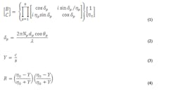
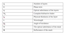
The relations that dictate the total reflectance of a multi-layer thin film structure are given in Equations 1 - 4:
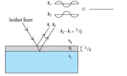
While the wavelength of light and angle of incidence are usually specified, the index of refraction and thickness of layers can be varied to optimize performance. Changes in any of these will have an effect on the path length of the light rays within the coating which, in turn, will alter the phase values as the light travels. This effect can most simply be explained through the example of a single-layer anti-reflection coating. As light propagates through the system, reflections will occur at the two interfaces of index change on either side of the coating. In order to minimize reflection, we would like to have 180° phase shift between these two reflected portions when they recombine at the first interface. This phase difference directly corresponds to a λ/2 shift of the sinusoid wave, which can best be accomplished by setting the optical thickness of the layer to λ/4. Refer to Figure 2 for an illustration of this concept.
Figure 2: 180° Phase Shift between Two Reflected Beams
Index of refraction not only influences optical path length (and thus, phase), but also the reflection characteristics at each interface. The reflection is defined through Fresnel's Equation (Equation 5), which provides the amount of reflection that will occur from the refractive index change at an interface at normal incidence.
About Sponsor
Edmund Optics is a leading supplier of optics and optical components, designing and manufacturing a wide array of multi-element lenses, lens coatings, imaging systems, and opto-mechanical equipment. EO’s state of the art manufacturing capabilities combined with its global distribution network has earned it the position of the world’s largest supplier of off-the-shelf optical components. Customers can purchase items by calling 1-800-363-1992, via the catalog or the website at http://www.edmundoptics.com/
