Simplifying Laser Alignment
Aligning a laser beam can pose many challenges, but knowing certain tips and tricks can greatly simplify the process. For instance, the first step in aligning a laser beam is to ensure that the beam is collimated. If the laser source is a diode or fiber, this may require additional optical components and assemblies such as collimating or cylindrical lenses, fiber collimators, or an anamorphic prism pair. Before trying to align the laser, it is also critical to thoroughly understand laser safety procedures and have the necessary safety eyewear that is specifically designed to block the wavelength of the laser being used. Additionally, detection cards may be required to align non-visible lasers.
To align a laser beam, the angular and translational displacement of the beam must be controlled. This can quickly complicate the alignment setup by requiring multiple optical components that may take up valuable table space. There are two basic configurations that utilize kinematic mounts, though, that are effective and simple solutions for aligning lasers in space-sensitive applications.
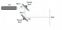
Parallel (Z-Fold) Configuration
Figure 1: Parallel (Z-Fold) Configuration
Figure 1 shows the basic setup, and demonstrates the reason behind the name, of the Z-Fold configuration. Two mirrors mounted on two kinematic mounts are used for angular displacement and positioned so that the incident beam hits the mirror surface at the same angle for each mirror. To simplify the setup, the two mirrors are placed at approximately 45°. In this setup, the first kinematic mount is used to get the desired vertical and horizontal position of the beam, while the second compensates for the angles. The Z-Fold configuration is the preferred method for aligning multiple laser beams on the same target. When combining lasers with different wavelengths, one or more of the mirrors may need to be replaced with dichroic filters.
To minimize the number of iterations in the alignment process, the laser should be aligned at two separate reference points. A simple cross hair reticle can be used, or even a white card marked with an X can be very helpful in the alignment process. The first reference point is at the surface, or as close to the surface as possible, of mirror 2; the second is the target. Use the first kinematic to adjust the desired horizontal (X) and vertical (Y) position of the beam at the initial reference point. Assuming a perpendicular beam is required, this should be the same XY position that is desired on the target. Once that position is achieved, use the second kinematic mount to compensate for the angular shift and align the laser beam on the actual target. The first mirror is used to get close to the desired alignment and the second is used to fine tune the alignment on the second reference or target.
Perpendicular (Figure-4) Configuration
Figure 2: Perpendicular (Figure-4) Configuration
The Figure-4 configuration is more complex than the Z-Fold, but can provide a more compact system layout. Similar to the Z-Fold setup, the Figure-4 layout utilizes two mirrors mounted on kinematic mounts. However, unlike the Z-Fold configuration, the mirrors are mounted at 67.5° angles which creates a ‘4’ shape with the laser beam (Figure 2). This setup allows mirror 2 to be placed away from the source laser beam path. Identical to the Z-Fold configuration, the laser beam should be aligned at two reference points, with the first reference point being at mirror 2, and the second at the target. The first kinematic mount should be used to move the laser spot to the desired XY position on the surface of the second mirror. The second kinematic mount should then be used to compensate for the angular displacement and fine tune the alignment on the target.
Regardless which of the two configurations is used, following the above process should minimize the number of iterations needed to achieve the desired results. With the right tools and equipment and a few simple tricks, laser alignment can be greatly simplified.
About Sponsor
Edmund Optics is a leading supplier of optics and optical components, designing and manufacturing a wide array of multi-element lenses, lens coatings, imaging systems, and opto-mechanical equipment. EO’s state of the art manufacturing capabilities combined with its global distribution network has earned it the position of the world’s largest supplier of off-the-shelf optical components. Customers can purchase items by calling 1-800-363-1992, via the catalog or the website at http://www.edmundoptics.com/