Targeted software rises to the MEMS design challenge
Larry Mosiman
In the race to develop microelectromechanical systems (MEMS) for optical applications, choosing software tools developed specifically for MEMS design can provide substantial advantages relative to time to market, development costs, and risk reduction. Optical MEMS can be designed using standard mechanical CAD (MCAD) or electronic design automation (EDA) tools. But unique characteristics of MEMS devices such as multiple physical domains, manufacturing processes, and scaling present unique challenges. In addition, software that supports a top-down design methodology can play a crucial role in fast and accurate MEMS development.
Software tools
Standard mechanical CAD tools have been available for many years to design and analyze a wide range of mechanical structures, from bridges to automobiles to HVAC systems. The tool's design capabilities include three-dimensional (3-D) layout, parts list generation, the ability to examine structures from any angle, and other functions necessary to design mechanical structures for manufacturing. Analysis capabilities use finite element modeling at the part or subassembly level and typically provide results for displacement, stress, resonant frequency, and other factors.
Electronic design-automation tools are used for high-level design of electronic components. They use standardized libraries of common elements that serve as building blocks to facilitate the design of complex electronic components. These tools perform higher-level design functions than MCAD tools because they use standardized design elements and manufacturing processes.
Software developed specifically for MEMS design combines the design and analysis capability of MCAD tools and the system-level design capabilities of EDA tools to provide a comprehensive and optimized environment for MEMS design.
Unique characteristics
Several unique characteristics of MEMS devices present challenges that can't be met by conventional MCAD and EDA software. A typical MEMS consists of several physical domains, including mechanical, electrostatic, thermal, piezoelectric, electromagnetic, optical, and others. Each domain has the potential to significantly impact device performance. For example, if the contact of a radio-frequency switch is deformed by residual stress, the electromagnetic performance can be affected. With MEMS design software, a mechanical analysis can calculate the deformation caused by residual stress and a subsequent electromagnetic analysis can provide insight into overall switch performance.
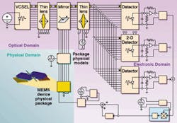
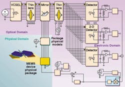
FIGURE 1. An optimized design approach uses system requirements as input parameters for system-level simulation. Parametric behavioral models, including electromechanical and optical models are used to build a model of the system. Simulations are performed to evaluate the behavior of the MEMS device within the surrounding system environment. Upon the successful completion of system-level simulations, detailed analysis of critical design areas of the MEMS device is performed using fine-element modeling or other established methods.
The scaling for MEMS devices is in the micron range, whereas conventional mechanical design generally starts in a range 10 to 100 times larger in scale. As a result, MCAD tools are cumbersome for MEMS design and may not be able to fully analyze effects at the micron scale. Microfabrication and packaging effects must also be considered during the design process. Because most MEMS devices are batch fabricated using processes similar to integrated-circuit fabrication, MEMS design tools use two-dimensional (2-D) layout and a manufacturing process emulator to build the 3-D device layer by layer. This ensures that the construction of the MEMS device will be compatible with foundry processes. Capabilities under development include MEMS-specific design rule checking, which will further improve the efficiency of the design process.
Top down vs. bottom up
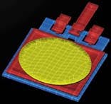
Designers of MEMS also must choose an appropriate methodologyeither a conventional, bottom-up, full custom-design or a top-down, structured custom-design methodology. With a conventional, bottom-up MEMS-design methodology, the designer starts by generating a 2-D layout and then adds fabrication processes to create a 3-D model. Three-dimensional models also can be created using a 3-D layout tool, but this is generally not recommended because designs created outside the context of fabrication processes may not be capable of being fabricated. With MEMS-specific design tools, meshed solid models for physical analysis can automatically be created from the 2-D layout. Physical analysis (finite-element modeling or boundary-element modeling) can then be performed to optimize the design. The process of performing this analysis can be quite time-consuming, but it can greatly improve the probability of success and reduce the number of fabrication cycles required to complete the MEMS design.
In contrast, with a top-down, structured custom MEMS-design methodology, the designer uses parametric behavioral models of MEMS devices to construct a system-level model and evaluate the device behavior along with the interaction of the MEMS device within its surrounding system (see Fig. 1). The parametric behavioral models serve as building blocks for the MEMS device, with models available for electromechanical, optical, electrical, as well as several other domains. They are combined to produce the desired device structure, and are parameterized in both geometry and material properties. These parameters can be swept during simulations to provide design curves and sensitivity analyses.
With this methodology, system-level evaluation can include the MEMS device, optical elements, electronic control circuitry, environmental effects, signal conditioning, and packaging. Performance is evaluated and the data are used to provide input for further refinement of the MEMS device, as well as the design of other subsystem components. For example, optical behavioral models can be placed at arbitrary locations and orientations in space to create a complete 3-D optical system (see Fig. 2). The designer, therefore, can rapidly converge on an initial design that is more thoroughly analyzed and in a fraction of the time it takes using conventional methods. Once the initial design is completed, detailed physical analysis can be performed on critical areas of the design. The amount of physical analysis required is much less than in the conventional, bottom-up design methodology, leading to an overall design process that is significantly less time-consuming.
LARRY MOSIMAN is senior product marketing manager at Coventor, 4001 Weston Parkway, Cary, NC 27513; e-mail: [email protected]


