Freeform Optics Design: Optical design challenges in virtual and augmented reality
ERIN ELLIOTT, KRISTEN NORTON, and MICHAEL HUMPHREYS
It’s been known for years that aspheric and freeform surfaces can improve the performance of an optical system—in theory. But over the last 30 years, advances in optical fabrication and measurement have pushed aspheric and freeform optical surfaces from design theory to reality. Optical fabrication companies are demonstrating that these optics can be reliably produced. This is enabling a new generation of complex optical surfaces that are revolutionizing the tech industry, making virtual reality (VR) and augmented reality (AR) headsets possible.
Emerging technologies: Virtual and augmented reality
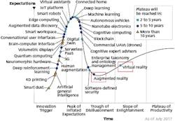
Virtual reality and augmented reality are often referenced in the same phrase, but these two technologies are in different stages of development. The Gartner Hype Cycle (see Fig. 1) shows the difference between the two stages.
According to Gartner, the “Hype Cycle is a graphical depiction of a common pattern that arises with each new technology or other innovation.”1 As shown in Fig. 1, AR sits in the Trough of Disillusionment phase, while VR is out of the trough and on its way to the Plateau of Productivity phase. Freeform optics are used in both VR and AR optical designs. Although freeform optical design is challenging, AR poses some unique challenges.
Example: An AR headset design
Figure 2 shows an example optical design for one eye of an AR headset. Each eye requires two freeform prisms; a full headset uses four prisms. Light from the microdisplay is relayed to the eye through Prism A. Light from the real-world scene is transmitted to the eye through Prism B and then Prism A. At the eye, the wearer of the headset sees the microdisplay overlaid on the real scene.
The light path through Prism A is complex. Light from the microdisplay first passes through surface A1. The beam undergoes total internal reflection (TIR) at surface A3 and then is reflected from surface A2, which is coated so that it is partially reflective. Finally, the beam from the microdisplay is transmitted back through surface A3 to reach the eye.
Surface A1 in Prism A is typically the most complex freeform shape because it’s the only surface that does not affect the real scene. The high level of asymmetry in the vertical axis and the short track length make this freeform surface insufficient to relay a high-quality image from the microdisplay to the eye. Therefore, like most AR prism designs, this example uses freeform shapes on all three surfaces of Prism A.
Prism B is required to deliver an unaberrated beam from the real-world scene to the eye. Surface B2 on Prism B is a freeform shape that matches surface A2 so that the two prisms can be cemented together. Surface B1 must be a freeform shape to correct aberrations that are introduced to the scene by Prism A and to correct the pointing so that the scene doesn’t appear to be shifted from its real location.
The complexity of this optical design is one reason that Gartner places AR technology in the Trough of Disillusionment phase.
Designing for headset size and weight
One of the prevalent challenges in both the VR and AR industries is the pursuit of smaller and lighter headsets.2 Reducing the size and weight of the headsets makes them more comfortable to wear. Optical designers are pursuing designs that use more extreme freeform shapes to achieve thinner, lighter prisms. Designers are also experimenting with lighter, higher-index materials, and optical components like holographic lenses.
System size, volume, and weight can be calculated directly and considered during system optimization of an optical design. Optical-design software packages now support dozens of freeform surface types, such as biconics, toroids, Zernike polynomials, and Chebyshev polynomials. The prism surfaces shown in Fig. 2 were designed using an Extended Polynomial sag equation in Zemax OpticStudio, which supports up to 230 terms in x and y polynomials.
Higher-order polynomial coefficients are required to correct aberrations, but the increased number of optimizable parameters has two drawbacks: increased optimization time and complexity of the optimization parameter space. Sequential ray tracing in OpticStudio is already highly computationally efficient. In a complex parameter space, though, the optimizer is more likely to get trapped in local minima. For that reason, a designer using freeforms must limit the number of parameters that are free to vary during optimization in a sensible way. New optimization tools designed to avoid local minima, such as Hammer or Global Search in OpticStudio, are also useful.
Advanced software analysis tools are also critical for improving the AR prism design. Two-dimensional plots of the surface sag, such as the Surface Sag and Sag Table analyses in OpticStudio, are needed for visualizing complex surface shapes. The plots must be generated with high sampling so that freeform surfaces with higher spatial frequencies are represented accurately. Plots of the surface curvature and slope are also useful, such as the Surface Curvature and the 2D Universal Plot analyses in OpticStudio. During manufacturing, many freeform surfaces are tested interferometrically using a computer-generated hologram (CGH). The resolution of the CGH limits the maximum possible slope of the freeform surface (minus its best-fit sphere). Designers must apply this slope constraint when optimizing the freeform surfaces.
The AR headset example has one plane of symmetry, but many freeform systems have none. Analyses of the system performance, such as root-mean-squared (RMS) spot size vs. field angle, can no longer include assumptions about axial symmetry—the system’s performance must be checked over a full range of field points in two dimensions. In addition, the system performance can vary significantly and nonlinearly with field position, so it is critical that the field of view is sufficiently sampled. For this reason, OpticStudio recently increased the number of allowable field points to more than 200.
Projected images
For most AR systems, the virtual image must be superimposed with real-world scenery. For some applications, such as a head-up display that shows an instrument gauge in a car, the exact position of the projected image in the real world is not critical. For other AR applications, the position of the projected image must be precisely controlled. This is often done by adding a camera to the outside of the headset that images and analyzes the world to determine where the projected image should appear.
In all cases, both the projected image and the real-world image must be crisp and undistorted. Optical-design software packages must allow the designer to simultaneously evaluate the system performance for both paths and to consider both paths during an optimization. In OpticStudio, this is done using multiple configurations, with one configuration for each beam path. Targets for RMS spot size, distortion, and beam pointing can be included for both beam paths in the merit function used for optimization.
Stray light considerations
Another difficult problem involves minimizing stray light in AR headsets so that the user doesn’t experience eye fatigue. Figure 3 shows an example of a stray-light pattern that would reach the eye in the AR headset example. Some problematic “hotspots” can be seen in the analysis.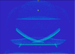
The stray-light pattern can be affected by many things, including the design of the freeform surfaces, the surface finishes and coatings used, the design and materials of the headset housing, and the lighting conditions in the real-world scene. Optical design software used in stray light analysis must consider all these effects.
The non-sequential mode in OpticStudio supports stray-light analysis. Optical designers can apply finishes and coatings to surfaces, import CAD models of the housing into the system, and use different kinds of illumination. Optimization of the freeform surfaces and system geometry can minimize the amount of stray light that reaches the eye.
Solving stray-light problems requires close coordination between the optical and mechanical models. In fact, bringing any product to market requires close coordination between optical, mechanical, structural, and materials engineers. Sophisticated software tools encourage that coordination and work to unify the disparate software tools used by each discipline. For example, mechanical engineers can use LensMechanix (also by Zemax) to design mechanical components around optics loaded from OpticStudio, and then evaluate how those parts impact the optical performance of the system. LensMechanix is part of the Zemax Virtual Prototyping software suite,3 which enables optical and mechanical engineers to create a virtual prototype of an entire system during a product’s design phase—decreasing the time to market.
Changes in manufacturing techniques, measurement, and software are making a new generation of freeform optical surfaces possible and influencing the speed at which AR and VR products get to market. However, there are still design challenges that must be overcome for VR/AR technology to become mainstream. Industry experts agree that we’ll get there—and that even though AR may not pull out of the Trough of Disillusionment phase just yet, optical design for AR will likely see some significant innovation in the next few years.
REFERENCES
1. See https://goo.gl/pN6qeF.
2. See https://goo.gl/QbauQQ.
3. See https://goo.gl/HFTmtx.
Erin Elliott is an optical research and prototyping engineer, Kristen Norton is the OpticStudio product manager, and Michael Humphreys is a senior optical engineer, all at Zemax, Kirkland, WA; e-mail: [email protected]; www.zemax.com.