Algorithm determines efficiency of fiber-coupling calculation
BOYD V. HUNTER
Diffraction-capable beam propagation in commercial optical design and analysis software is a significant feature that enables a user to perform sophisticated and meaningful fiber-coupling (and other) analyses. However, this is often a relatively new feature and can require a high degree of user intervention and monitoring if reliable results are to be obtained.
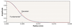
For engineers accustomed to the speed and reliability of spot-size calculations, the reliability and difficulty of calculating an optically simple system such as fiber-coupling efficiency using collimators, comes as a rude surprise. Most programs treat the beam from a single-mode fiber as a Gaussian beam. This is a convenient approximation that introduces little error (see figure). However, the quality of the approximation is wavelength-dependent and this, along with wavefront aberrations, will alter the insertion-loss (IL) curve relative to the paraxial result.
That said, there are two basic algorithm types: geometrical ray-trace approximations and physical optics propagation (POP). The former are often easiest to implement and use; unfortunately ease of use and accuracy are often inversely correlated.
Fiber-coupling algorithms
The first algorithm widely implemented was based on the 1982 paper of Wagner and Tomlinson.1 Based on the ray-trace, the overlap integral between the source and receiver electric fields is calculated in the exit pupil plane. This algorithm, however, does not capture diffraction along the optical path. The only effect well modeled by this algorithm is beam size/shape mismatch.
The second algorithm uses the point-spread function (PSF) calculated by the direct (or Huygen's) integration of the ray-trace engine's wavefront error as the input field in the overlap integral. This technique can only work with the system at focus; the defocus required for paraxial Gaussian-beam propagation must be removed. Again, diffraction along the optical path is not captured by this algorithm. Thus this approach cannot calculate IL vs. separation; however, beam shape/size mismatch and tilt are handled well.
The third algorithm decomposes the beam into a series of small Gaussian beamlets, similar to angular decomposition. Parabasal rays are used to determine the effect of surfaces and diffraction on each of the small Gaussian beamlets. The beamlets are recombined at the image surface to determine the final wavefront.2 This algorithm tracks the effects of diffraction as the beam propagates. This technique is a ray-trace approach; the rays are launched to mimic waist diameter and divergence for each beamlet. The algorithm should be appropriate for any problem and was the only ray-trace approach that matched our POP results.
The fourth algorithm, POP, does a full propagation of the electromagnetic fields; thus aberrations, vignetting, and diffraction are considered. In principle, this makes it ideally suited for all coupling problems. There are three issues, however, which limit the application of POP. First, transitioning from near-field to far-field propagation techniques in a homogeneous medium can lead to unphysical IL discontinuities. Second, propagation through a refractive, diffractive, or reflective surface, or through an inhomogeneous medium; ray-trace results are the basis for a transfer function to construct the amplitude and phase information needed to continue propagation.3 And last, it is much slower than ray-tracing. Any surface with large wavefront errors will force a fine sampling grid—it is not hard to overwhelm an otherwise amply equipped computer. Problems are often discovered by examining the beam at each surface. In short, the technique requires vigilance and alertness on the part of the user—more than required by most other problems.
Typical problem cases
Test cases were prepared to span the range of common problems and probe the effectiveness of each algorithm (or its implementation) as found in commercially available optical-design software. Detailed results (omitted here) and lens prescription files are available for download.4
Single-fiber collimators: In predicting IL vs. separation for two identical collimators, only POP and the Gaussian-beamlet approaches work well because they track the waist locations. A theoretical curve can be obtained from März:
IL = 10log |(1 + |(2Dzr)|2)|
where zr is the Rayleigh range and Δz is the working distance change from the IL minimum.5 In our case, using LightPath Technologies (Orlando, FL) T4300 collimator design with Gaussian-beam waist 100 mm from the lens, the theoretical curve tracks experiment only if we multiply the theoretical values by 2.4; we have seen other cases in which the multiplier is approximately 1.4. This suggests some physics in the experiment not captured by the model of a propagating Gaussian beam. My suspicion is that aberrations due to lens surface-figure errors or fiber distortions are the culprits.
Dual-fiber collimators: In the case of IL vs. lens-to-mirror separation for a dual-fiber collimator (the lens has an angled facet for return-loss control), the IL minimum will occur when the system is telecentric (the mirror is a focal length from the front principal plane). Coupling-efficiency errors are primarily due to angular misalignment of the beam on the receiving fiber. The lens is typically a gradient index lens from LightPath, NSG (Osaka, Japan), Corning (Corning, NY), or Grintech (Jena, Germany).
The direct-integration algorithm worked perfectly. Wagner-Tomlinson failed as did some POP implementations, suggesting implementation difficulties due to either the gradient index, angled facet or sign reversal/reverse propagation. No test data was available for the beamlet algorithm. As a side note, many programs generate incorrect Gaussian-beam data for this problem. One issue is that the angled surfaces distort the paraxial calculations.
Laser diode to single-mode fiber: In the problem of selecting the right lens combination to couple a 2:1 ellipticity diode beam into a fiber, the dominant issue in the coupling efficiency will be the beam size/shape mismatch. In this case the IL vs. radius response curve is quite flat; hence the different predicted optima may not be empirically distinguishable. Wagner-Tomlinson, Direct, Beamlet, and POP algorithms are, in principle, capable of handling this problem. Because of the flat response curve, results were often similar but with clear instances of implementation problems. High aberration surfaces in my particular setup made POP difficult—it took several tries to get reasonable results. Access to experimental data was limited; however, for an analogous problem in a commercial setting, the OpTaliX Wagner-Tomlinson coupling-efficiency prediction differed from the experimental data by 1%.
Multimode fibers: In principle, POP with appropriate field distributions is the best choice for multimode fibers, although setting up the field distributions may be nontrivial. Eigenmode calculations initiated to support this article made impressively accurate modeling possible. An easier—but limited—approach is to use an extended or pixelated source. The source size and NA are dictated by the fiber core properties. The receiving fiber is modeled with an image plane aperture the size of the core PLUS either an NA constraint on the receiving fiber or a hard aperture in the system to approximate the receiving fiber NA. Calculate the fraction of rays that pass through the system and, voilà, the coupling efficiency is calculated. Be forewarned that this technique assumes that all fiber modes are excited, a condition that may not be met in practice and effectively treats the fiber as a step-index fiber.
ACKNOWLEDGMENT
This work would not have been possible without the cooperation and assistance of many people, particularly: Fritz Blechinger (Optenso; Igling, Germany) for OpTaliX modeling and for discussions about POP and fiber coupling efficiency calculations; Dave Hasenauer and Jake Jacobsen (Optical Research Associates; Pasadena, CA) for CODE V modeling; Ken Moore (ZEMAX Development Corp.; San Diego, CA) and his staff for reviewing my ZEMAX models; Marie Côté (Breault Research; Tucson, AZ) for ASAP modeling; Rich Pfisterer, Steve Johnson, and Scott Ellis (Photon Engineering; Tucson, AZ) for some OSLO and FRED modeling; and Kevin Walter and John Telle (formerly at LightPath Technologies) for the experimental data. And finally, my wife for her support and patience.
REFERENCES
- R. E. Wagner and W. J. Tomlinson," Applied Optics 21(15), 2671 (1982).
- A. W. Greynolds, Proc. SPIE 560, 33 (1985).
- ZEMAX User's Guide, Chapter 21, (April 4, 2002).
- http://www.optenso.de/download/download.html
- Reinhard März, Integrated Optics: Design and Modeling, 140, equation 5.26 (Artech House: Boston, 1995).
Boyd V. Hunter represents Optenso in North and South America, 11127 Jordan Ave. NE, Albuquerque, NM 87122; e-mail: [email protected].