Software tools speed optical thin-film design
JENNIFER D. T. KRUSCHWITZ
Thin-film-design software packages have become very powerful and versatile in the last ten years. With the many options now available, it is helpful to review some of the software tools and the advantages they offer to the thin-film designer.
Environment
The term "environment" in optical thin film design refers to the index of the medium and substrate, the illuminant, the incident angle of incoming illumination, and the detector that are associated with the optical system where the thin film design is being used. Dedicated software packages equip the user with a database of different illuminants (CIE illuminant data, equal intensity, and thermal blackbody radiators) and detectors (equal responsivity, photopic, scotopic), and some packages allow the user to define their own illuminants and detectors.
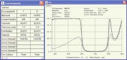
The TFCalc 3.5 package has a new environmental feature called "Active Layer." (Active layer is referred to as "Material Substitution" in the Design category of the table.) Since the designer can utilize multiple environments when designing and optimizing in TFCalc, different film materials can be used within a given design for different environments. For instance, a red color mirror design can be made a with multilayer stack of tantalum oxide (Ta2O5) and silicon dioxide (SiO2) (see Fig. 1).
Tantalum oxide has the notoriety of having absorption in the visible region unless it is baked at high temperatures. Using TA2O5A as Ta2O5 with absorption and TA2O5B as the same material after baking out the absorption, the designer can see what the red mirror design will look like before and after baking by just changing from Environment 1 to Environment 2. This neat feature can be used for any material whose index of refraction changes under some external environmental change (such as water adsorption or temperature).
Materials
The Materials category focuses on the properties of the individual film layers to be used within a design. All of the software packages contain a common materials database for the designer. If there is a material that the designer believes is missing from their software listing, a simple phone call or e-mail to their prospective software vendor can fix the situation. All of the vendors will either send the users a data file to insert into the software, or refer the user to an article or paper that contains the data needed.Beside common materials, a package could contain ways to define a material. Anisotropic materials can be defined as birefringent or as a material mixture. Variable index is one that is calculated by the software. Packing density describes the density of the film after deposition, and usually combines the bulk material properties with that of air. Some of the software packages can utilize a material other than air to create a film that is a mixture. Ian Stevenson at Denton Vacuum (Moorestown, NJ) uses Essential Macleod. "The ability to adjust both packing density and void content is a powerful feature," he said. "It allows a single material table to be used to describe the variations in index values that can arise from different layer thicknesses, changing deposition conditions and from one machine to another."
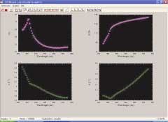
Refractive index (both real, n, and imaginary, k) can be extracted from spectral or ellipsometric data gathered from a particular coating machine. A Film Wizard model shows the extraction process for a titanium nitride (TiN) film on silicon from ellipsometric data, psi (Ψ) and delta (Δ) (see Fig. 2). The extraction process incorporates some of the refinement methods contained in the software, and this handy feature can also be used with spectrophotometer and spectrometer traces that are imported directly into the software.
Design
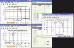
When configuring a design, there are two nomenclatures used to describe the thickness of a layer: physical thickness (Å, nm, or µm) and optical thickness. Optical thickness is described in quarter waves of the designing wavelength as either a quarter-wave optical thickness where 1.0 equals a quarterwave or as full-wave optical thickness where 0.25 equals a quarter wave. Designs can be entered as formulas or as individual layers. In addition to the default homogeneous thin layer, the layer types can be described as massive (substrate-like) or inhomogeneous (where the index changes as a function of thickness).Two conveniences that the software can provide to the designer are material substitution and ignore functions. Material substitution provides a simple interface for replacing materials within a given design, without the aggravation of cutting and pasting individual layers. The ignore function in Filmstar allows the user to view specific sections of a design or a series of designs separately by just ignoring the appropriate layers (see Fig. 3). Without the ignore function, the designer must remove the layers manually and replace them when he or she wants to view their performance.
Refinement
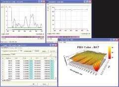
For a program to refine a design, the user must define performance targets. A target generator can allow the user to generate many individual targets over a broad range easily. The refinement program can also allow the user to constrain the layer thickness of individual layers while trying to reach the goal targets. Several variables can be used in the refinement process: refractive index of each layer material; tooling factor (within the crystal monitors); and layer thickness and individual layers can be grouped together and refined as a unified body. Refinement methods can be constrained or unconstrained to give the software free reign to reach the desired targets. The numerical methods are described in 0th order (no derivatives), or 1st and 2nd order. Jim Oliver at the University of Rochester (Rochester, NY), uses Optilayer. "It provides a simple method of selecting good starting designs for further refinement or error analysis, without using other programs or saving and loading multiple design files," he said.Synthesis describes how the software adds layers to create the optimum design when an acceptable solution has not been found using refinement alone. Using the Refinement and Synthesis methods in Optilayer, a polarizing beam splitter (PBS) using a BK-7 cube at 45° was originally designed with a 30 layer starting design of alternating Al2O3 and SiO2. The targets used in the refinement process consisted of the transmission for p-polarization for incoming light at 45° and 38° as well as a user defined target (UDT) of the transmitted p-polarization divided by the transmitted s-polarization (Tp/Ts; see Fig. 4).
Analysis
In analyzing a birefringent coating, Multilayer asks the designer multiple questions that include describing the type of materials used (isotropic, anisotropic, magneto-optical, and so on), the direction of dielectric tensors, and then the designs environment. The software calculates the Fresnel coefficients and then allows the user to plot the reflectance, transmittance, or phase of different illuminant polarization states.
Other analysis functions that are important to the designer are an active cursor to navigate a data plot, color mapping to interpret calculated color, an interactive plot (or an animated plot), and 3-D mapping of the data. Paul Meier-Wang of Accucoat (Rochester, NY) utilizes the animating features in TFCalc. "The ability to animate the performance of a design [at different angles, for example] is beneficial to show customers what they can expect from their coatings when they use them in the field," he said.
Manufacture
Software now also has the ability to guide the designer through manufacture. If the coating equipment used for the manufacture of the design has an optical monitor, that optical monitor may be single- or multiple-wavelength driven with multiple chips and/or monitor spots. Depending upon what the monitor-to-work ratios are for a particular machine, a designer may need to specify a tooling factor for each material being deposited. Then, before deposition even begins, a simulation of the optical monitor strip-chart can be reviewed as another guide to design manufacture.If a machine is not equipped with an optical monitor, some software programs can produce simulation based on particular crystal monitor equipment. Run sheets can be produced quickly for the designer to aid in the efficiency of manufacture. Rob Sczupak, from Barr Associates (Westford, MA) uses Filmstar's user-defined run-sheet function.
"I was able to create equipment-specific run sheets within the software and now I have all of the information ready for printing when my designs are ready for manufacture," he said.
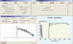
Finally, can the software simulate the design over many runs utilizing all of the individual errors associated with different parts of the coating equipment? Using the simulator routine in Essential Macleod an edge filter was designed and is going to be deposited in a coater with an optical monitor (see Fig. 5). Macleod's simulator package allowed the user to specify signal error and overshoot error for that particular machine. Ten runs were simulated and the final spectral curves from the analysis show that some equipment adjustment may be necessary before the real deposition should take place. This feature is invaluable in saving the designer and manufacturer from producing product that may be out of specification without equipment refinement.
PROCEDURAL NOTES
Six software packages dedicated to optical thin-film design are included in this survey. Other software packages, particularly lens- and optical-system design software, also have features for thin-film analysis, but not as in-depth as those found in dedicated software.
For each category, one software package interface is highlighted. Client comments about favorite software utilities are also included. For each interface highlighted, a basic design problem was created and solved in each software package. So the highlighted functions may also be obtainable with the other software packages, but limitations of space precluded highlighting all six packages in each category. So the highlights are intended to illustrate functions rather than to suggest that any particular software package is preferable in any particular category.
ACKNOWLEDGMENT
The author extends a hearty thanks to Angus Macleod and Chris Clark representing Essential Macleod; Fred Goldstein representing Filmstar; Javier Ruiz and Emad Zawaideh representing FilmWizard; Masud Mansuripur representing Multilayer; Gary DeBell, Alexander Tikhonravov, and Michael Trubetskov representing Optilayer; Tony Noe representing TFCalc.
Jennifer D. T. Kruschwitz is the principal of JK Consulting, 33 Elmore Rd., Rochester, NY 14618; e-mail: [email protected].
