Software tool boosts beam analysis efficacy
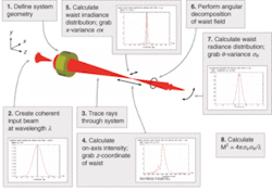
Laser beams in real applications usually pass through complex delivery systems on their way from the source to the target. Regardless of how perfect the beam quality is starting out, the on-target beam quality can be seriously degraded by system aberrations and misalignments. It is the job of the optical system designer to know what the delivery system will do to the beam quality. High-quality optical design software can play an essential role in providing this knowledge (see "Calculating M2," [below]).
In the feasibility phase of a design project, a first-cut beam-quality assessment is necessary to ensure system performance requirements can be met. In the design phase, a detailed beam-quality analysis is needed to tolerance the individual optical components and their mechanical integration into the final assembly. For complex systems, this is when design software becomes indespensible.
Probably the most widely used measure of laser beam quality is the M2 metric.1, 2 M2 is defined by the equation
M2 = 4πσxσθ/λ
where σx and σθ are, respectively, the standard deviations of the irradiance (flux per unit area) and radiant intensity (flux per steradian) distributions. The M2 metric can be applied to any laser beam, ideal or nonideal. For an ideal Gaussian field distribution, σx = ω/2 and σθ = θdiv/2, where ω is the spot size and θdiv (λ/ρω is the far-field divergence angle. Thus, M2 = 1 is the limiting case for an ideal Gaussian beam. For nonideal beams, M2 is greater than 1. An M2 of less than 2 is often considered to be "good" (that is, "less than twice the diffraction limit"). A value of M2 ≤ 1.1 is usually considered to be "perfect" for all practical purposes.
Three examples
In validating an application for any design tool, it is a good idea to test it on cases that can be solved analytically. The three examples that follow compare analytically obtained solutions to solutions calculated using ASAP (Breault Research Organization; Tucson, AZ). The first example looks at the effect of aberrations on an initially ideal Gaussian beam. The second and third examples look at effects that can arise when multiple beams are combined.
Spherical aberration. The M2 degradation due to spherical aberration of a singlet lens can be calculated analytically. Assuming an initially collimated ideal Gaussian input beam, the analytically derived M2 for the focused beam is given by
null
where λ is the wavelength, ƒ is the focal length, and C4ƒ is a dimensionless parameter that depends on the index of refraction, the lens figure, and the wavefront curvature of the incident beam.3
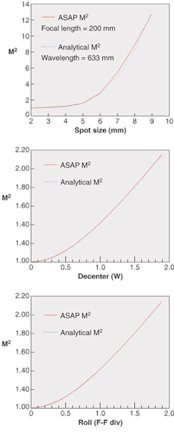
This example assumes a collimated Gaussian beam incident on a 20-cm-focal-length plano-convex singlet lens at a wavelength of 633 nm. To aggravate the spherical aberration, the lens has been misoriented with the flat side facing the incident beam. Assuming an index of refraction n = 1.5, C4ƒ = 1.125 (for a properly oriented lens, C4ƒ = 0.292). In this case, the calculated variation of M2 with initial spot sizes fell within 10% of the analytical result (see Fig. 1, top). The agreement could likely be improved, but as it stands it is probably comparable to the reproducibility of typical M2 measurements in the lab. The optical engineer will usually spend most of his or her time and effort trying to get M2 below 1.5 and hopefully below 1.2.
Decenter. Many laser systems involve multiple beams. When two beams are combined, linear decentering can occur. In this example two Gaussian beams are combined incoherently. It is not hard to derive an expression for the dependence of M2 on decenter. For decenter of two incoherently combined beams (that is, two beams at different wavelengths) the following expression yields the M2 of the combined beam:
null
where Δ is the linear decenter and ω is the spot size of the (assumed to be identical) input beams. Analytical and software solutions yielded similar results (see Fig. 1, center).
Roll. When two beams are combined, relative pointing error, called roll, may also result. The analytical result looks very similar in form to the one for decenter.
null
where δ is the roll angle and θdiv is the far-field divergence angle, which equals &lambda/πω. As in the previous example, analytical and software calculations produced similar results (see Fig. 1, bottom).
These examples are simple demonstrations of a few of the possible aberrations that can befall a laser beam in an optical system. Because the effects of simple perturbations can sometimes be calculated by hand, one might ask why bother to use software. The answer is that real systems can involve multiple beams, and the compounding of several types of beam aberrations and misalignments can easily generate a level of complexity that is not amenable to analytical modeling.
Spectral beam combining
Spectral beam combining (also known as wavelength beam combining or incoherent beam combining) has attracted interest in recent years as a means to scale the power of multiple emitters while preserving beam quality comparable to that of a single emitter.4, 5, 6 In this technique, an array of emitters, either an array of fiberoptic amplifiers or a bar of laser-diode optical amplifiers, is coupled to an external cavity. The emitters are highly reflective on the back side and antireflection-coated on the side facing the cavity.
The cavity serves two purposes. First, it provides a separate feedback path to each emitter, so that an array of external-cavity lasers is formed. Second, the wavelength of each external-cavity laser is automatically locked to a different wavelength so that the diffracted beams from all the external-cavity lasers are collinear. Thus, the grating performs the functions of feedback and wavelength multiplexing. Many complications arise that can potentially disturb the ideal situation just described. Consequently, designing spectral-beam-combined lasers and modeling the impact on beam quality of aberrations, fabrication errors, and misalignments is beyond the scope of purely analytical methods and requires high-quality design software with M2 capabilities.
REFERENCES
- M. W. Sasnett, Physics and Tech. of Laser Resonators, 132, D. R. Hall and P. E. Jackson, eds, Adam Hilger, Bristol (1989).
- A. E. Siegman, SPIE Proc. 1224, 2 (1990).
- A. E. Siegman and J. Ruff, SPIE Proc. 1834, 130 (1992).
- V. Daneu, Proc. Conf. on Lasers and Electro-optics CLEO 2000, 242.
- T. Y. Fan, Aerospace Conf. Proc. 2000 3, 49.
- S. Augst, Conf. Lasers and Electro-optics CLEO 2002 1, 594.
At the time this article was written, PAUL ZORABEDIAN was a consultant for Breault Research Organization, 6400 East Grant Rd., Suite 350, Tucson, Arizona 85715, www.breault.com. Zorabedian can be reached at [email protected].
Calculating M2
The M2 calculations in this article were performed using ASAP (Breault Research Organization; Tucson, AZ). There is no "canned" M2 operator, but M2 calculations can be performed with a relatively small number of functions and operations that are intuitively similar to the procedure that would be performed in the lab. The steps are (shown graphically in figure):
- Set up the system geometry using the Builder or script.
- Set up input beam.
- Trace rays through system.
- Find position of beam waist.
- Calculate the standard deviation σx of irradiance distribution at the waist. Grab the value of σx from the control panel output.
- Perform an angular decomposition of the field distribution.
- Calculate the standard deviation sq of radiance distribution. Grab the value of sq from the control panel output.
- Calculate M2 using the equation M2 ≡ 4πσxσθ/λ.
null


