CLOAKING AND INVISIBILITY OPTICS: Ray-tracing software reveals imperfect invisible sphere
Aaron Danner, an assistant professor at the National University of Singapore, is helping to visualize what should ideally be invisible: optical cloaking devices. First of all, because practical versions of such devices do not yet exist—at least in the visible—Danner had to resort to software simulations. Second, because no software was available that could depict devices such as imperfect invisible spheres in photorealistic environments, Danner had to write the software himself.
While other simulations of invisibility devices exist, Danner wanted to see what the devices would look like as used in a real outdoor setting and also how they would appear when built using technical compromises.
He started with previously developed free software called POV-Ray, which creates photon-mapped ray traces through transparent objects of unvarying refractive index (even if the index is below 1, or even 0). But because cloaking optics are created from materials of gradient index and can be birefringent, POV-Ray was not usable. So Danner built upon previous methods, achieving polarized ray tracing in anisotropic, gradient-permittivity media.
An example was chosen of an invisible sphere in which all incoming rays circle the sphere's center once and then exit the sphere along the same path they entered. But a perfectly invisible sphere would be rather unexciting to depict. Instead, Danner chose a variation of the sphere that is of special interest because it is potentially easier to fabricate: a sphere that is invisible for only one, not both polarizations.
While a perfect invisibility sphere for use in the visible spectrum would have to be created from an optical metamaterial with the impractical property that all components of the permeability must equal those of the permittivity, a sphere that is invisible for only one polarization could be made from a gradient-index birefringent dielectric.
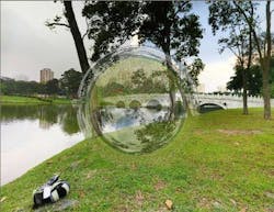
A sphere in the park
To make the calculations more straightforward so they could be done in real time, the rays are traced backward, from a virtual camera and through the sphere, from which they exit toward the background scenery. The camera is assumed to be a pinhole camera with no diffraction effects. The background panorama (the Chinese Garden in Singapore) was digitally stitched together from about 90 photographs taken from a camera on a tripod. The background was assumed to be infinitely far away to eliminate any parallax-related calculations (which would be convoluted enough that they would prevent real-time calculation).
The sphere depicted by the software (see figure) has a radially varying refractive index that varies from 1 to 9.46—not really possible to fabricate, but at least the potential is there. In fact, Danner believes that with some optimization, the sphere's refractive-index range could be shrunk to between 1 and 3.
The "half"-invisible sphere, with its one polarization passing through perfectly and the other polarization being redirected all over the place, looks somewhat like a photograph of a soap bubble. However, the details are quite different, with the distorted portion of the panorama being nothing like what would be seen if it were due to the reflection from a bubble.
The most practical purpose for this sort of ray-tracing software, as Danner notes, would be to visualize imperfect but easier-to-fabricate versions of invisibility and cloaking devices as they would be used in their real-life applications. Such visualizations would allow the device designer to find the right balance between the technical feasibility of the device and how close it is to ideal performance.
REFERENCE
- Aaron J. Danner, Opt. Exp. 18, 4, p. 3332 (Feb. 15, 2010).
About the Author

John Wallace
Senior Technical Editor (1998-2022)
John Wallace was with Laser Focus World for nearly 25 years, retiring in late June 2022. He obtained a bachelor's degree in mechanical engineering and physics at Rutgers University and a master's in optical engineering at the University of Rochester. Before becoming an editor, John worked as an engineer at RCA, Exxon, Eastman Kodak, and GCA Corporation.