Finite-difference time-domain method guides optical design of metallic nanostructures
During the past ten years, the finite-difference time-domain (FDTD) method has proven to be among the most powerful engineering tools for all areas of electromagnetic simulation.1 The method offers a unique combination of capabilities, through a single analysis, to model all wave effects including propagation, scattering, diffraction, reflection, and polarization. It can also model material anisotropy, dispersion, and nonlinearities without any a priori assumption for the wave equation and structure geometries. Recent research extends the FDTD method into advanced applications areas such as biophotonics, biomedical, and nanostructures.
Nanoscale wave optics becomes more complicated when metals are added to the traditional dielectric material system. The optical properties of nanoscale metals differ significantly from their bulk properties. The effect of metal on the optics is significant, and the material parameters of the metal are an important consideration, especially when metals are included in the design of photonic crystals.
One of the distinct advantages of the FDTD method is that metals can be added to the material system via the Lorentz-Drude models.2 However, traditional FDTD analysis for metal only considers the surface effect, so the inside of the metal is treated as a perfect conductor. This traditional method is not suitable for analysis of nanoscale optics, because the wave actually penetrates the inside of the metal, and will affect all the wave properties such as near field, far field, scattering, and diffraction. Integrating the Lorentz-Drude model for metal can enhance the FDTD method of analysis, so that it will include the EM field effects on particles at the nano level (see "FDTD approach for optical metallic material," p. 68). In addition, Optiwave's OptiFDTD software can simulate both internal and surface-wave effects of the metal within the nanostructure.
Two examples
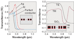
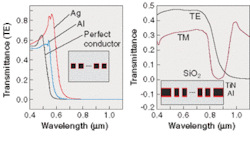
Metallic structures with typical dimensions below the wavelength of light are expected to show local enhancement of the electromagnetic field strength, which may affect the field effect dramatically (see Fig. 1).
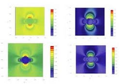
Spheres can be considered like a basic atom shape in nanostructures. Light-scattering simulations provide an efficient tool for studying nanoparticle morphology, in addition to the nature of scattering and its sources. The analysis of this information provides the basis for a better understanding and development of new optical methods for noninvasive biomedical diagnostics. FDTD-based software offers a potential for the simulation of light scattering from a single nanoparticle in situations in which other approaches either do not work, or their inherited approximations appear questionable (see Fig. 2).
FIGURE 2. These 3-D simulations consider a 39-nm radius spherical nanoparticle periodically positioned with a period of 24 µm, surrounded by air. Two types of material are simulated: a dielectric with refractive index of 1.47 (left) and the metal gold (right). The excitation is a y-polarized plane wave propagating in the z direction. The displayed results show the y-z plane field pattern (top) and the x-y plane field pattern (bottom). The enhanced model (bottom) shows more detailed wave effect in the edge of the metal object. The traditional method did not allow view inside the metal, yet the Lorentz-Drude-enhanced FDTD method displays more detail of inside effects. In addition, it allows for estimation of the far-field and the near-field pattern to determine the nanometallic layout design.
RICHARD ZHANG is a product manager and scientist and STEVEN DODS is a product manager and senior scientist at Optiwave , 7 Capella Court Ottawa, ON, Canada K2E 7X1; e-mail: [email protected]. PETER CATRYSSE is a postdoctoral scholar at Stanford University, Stanford, CA 94305.
REFERENCES
- A. Taflove and S. C . Hagness, Computational Electrodynamics—The Finite Difference Time Domain Method, 2nd Ed., Artech House (2000).
- A. D. Rakic, A. B. Djurisic, J. M. Elazar, and M. L. Majewski, Appl. Optics 37(22) 5271 (August 1999).
- S. D. Gedney, IEEE-AP 44 1630 (1996).
FDTD approach for optical metallic material
The significant advantage of the FDTD method is the great variety of materials that can be consistently modeled within the FDTD context. The metallic material which couples to the Maxwell's equation is the Lorentz-Drude model.2 This is described in the first published use of the advanced optical metallic material model developed for FDTD simulation.1 The Drude dispersive model for surface plasmon is written in the frequency domain as:
(1)
and the Lorentz Model as:
(2)
where ωp is the plasma frequency, m is the number of oscillators with frequency ωm and lifetime 1/Γm,
is the plasma frequency as associated with intraband transitions with oscillator strength G0 and damping constant Γ0. The above Lorentz and Drude Model can be expressed as a more general equation:
(3)
where εr,∞ is the relative permittivity at infinite frequency. In this general model; for m = 0, when we set ω0 = 0, this term becomes the Drude model as in (2). For m = 1 . . . M, when we let Ω1 = Ω2 = . . . = ΩM, it becomes the Lorentz model as in (3). This model can also work as separate Drude and Lorentz models.
For the purpose of FDTD analysis, relation (3) has to be transformed from the frequency domain to the time domain. This can be done by adopting the polarization-equation (PE) philosophy, so that the time-domain Maxwell's equation can be written as:
(4)
(5)
(6)
Using the finite-difference technique to solve equations (4) to (6), will generate the FDTD scheme. For example, the electric-field intensity (Ex) component in Yee's cell can be solved as
(7)
(8)
(9)
where J is auxiliary component to solve the Ex3. As for the boundary condition, by using Prof. Stephen Gedney's APML concept,3 the boundary condition can be derived in the same way, but more auxiliary components will be used.2


