'Macrofocal object' benefits automotive lighting design
State-of-the-art lighting systems in modern motor vehicles require new mathematical shapes to meet current automotive specifications and deliver the required lighting effect. Computer-based design of reflector and lens geometry is now common in the design process of all aspects of vehicle lighting because today's modern styling in both the front and back of autos often leads to extremely curved lenses. These extreme curves create light deviation and glare light for oncoming traffic.
Several design-tool options are available to automotive optics designers. Lucidshape is one example that implements two new algorithms—a Macrofocal Surface method and a Profiled Surfaces method—to solve these design problems. The Macrofocal Surface method quickly designs a starting point for high- and low-beam headlamps with sharp cutoff beam patterns and for fog lamps. The Profiled Surfaces algorithm is used to design reflectors and lenses in all kinds of signal lamps.
Software tools must provide the optimal mathematical algorithm to help an engineer design the perfect reflector or lens. Such tools must directly control the lighting function and not simply provide a set of parameters. For instance, if a designer wants to define an output spread-angle function for a headlamp with a specified beam pattern he or she first specifies the beam pattern desired, the general package size of the lamp, and which source (bulb) is being used in the lamp. The software then calculates the shape of the reflector automatically, saving hours of initial CAD and mathematical work. This eliminates the precalculation step of determining the radius of each flute element in the reflector—a step usually created in a CAD system.
For fast design iteration software design tools must also be able to quickly analyze a system, making possible closed optimization loops. Lucidshape offers speedy analysis of any reflector using a proprietary light-mapping method that traces millions of rays in seconds. Interactive ray-path display and light-source (filament) images give the designer additional feedback about the behavior of each shape.
Macrofocal objects
Some beam patterns, like an automotive low beam, need a sharp intensity cutoff at one or more sides of the beam. Such a pattern rim can be created with the concept of a macrofocal object—first introduced by Spencer and discussed by Elmer.1, 2
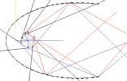
With a single focal curve or surface (parabola, hyperbola, ellipse, and so on) the reflector always directs one focal point to a desired direction or onto a target point. In the macrofocal concept each reflector point directs a particular edge position on the light source toward a desired point or direction. One can say that the focal point migrates around the emitter surface to produce results like a sharp cutoff rim (see Fig. 1).
In Lucidshape an object that behaves in a way that can deliver the right focal point for any reflector point is called a macrofocal object. The two major features of a macrofocal object are that it can create a convex hull, which is the silhouette of the light source seen from the reflector point; and that on the silhouette it can identify two extreme points
A macrofocal object can consist of several emitter surfaces. Each surface can have any free-form shape, not just simple cylindrical, spherical, or disk type shapes. The emitter sequence could be a row or pattern of light-emitting-diode (LED) disk surfaces that in sum have to create a cutoff line. The convex hull is created around all emitters.
In some cases the orientation of the surfaces plays an important role. A set of LEDs on a ring carrier can only partly be seen from a reflector point. The macrofocal object has to filter out invisible portions.
A set of free-form shield surfaces can also be included in a macrofocal object. A little cap in the H4/HB3 bulb, for example, was classically used to create the cutoff line. It creates a sharp edge in the luminance image seen from the reflector. The macrofocal object has to cut out the hidden portion of the light-emitter.
In some light sources the wire emits extra light or a second filament gives ghost light due to reflections. This and other effects can jeopardize the sharp cutoff line if the reflector was just designed based on a simple cylinder. With the macrofocal concept the design can be based on measured luminance images. The macrofocal object can identify an isoluminance line of, say, 20% in the measured data and build the convex silhouette. The luminance images can be represented as ray files.
In a free-form-lens surface calculation, light that comes through a second refractive surface must be considered. The macrofocal object has to deliver the virtual starting point of each incoming ray.
Design example: Cutoff beam pattern
To design a cutoff beam pattern with macrofocals the reflector surface is skinned over a fish bone-like set of curves (see Fig. 2). The spine curve controls the spread-angle range. The orthogonal "bone" curves take care of the sharp cutoff line. Each bone curve is a macrofocal curve consisting of a sequence of parabola or elliptical arcs. In the case of a "far-field" placement of the cutoff line, we have a parabola. If the cutoff is located on a plane in front of the headlamp, say at a 10-m distance, we are talking about a "near-field" application and the curve pieces are ellipses. The bone curves are also created with right side orientation. Otherwise the beam pattern looks like a "banana" bow.
A rich set of lighting-design tools is the driving power for innovative design work. New lighting ideas and challenges create new demands for software to extend an engineer's toolbox. Lucidshape is one example that has grown in terms of functionality over the years with daily project work. Hardware measurement of designed parts can help correlate software simulation refining the simulation/design process.
REFERENCES
- D. E. Spencer, L. L. Montgomery, and J. F. Fitzgerald, J. Opt. Soc. Am., 5 (January 1965).
- W. B. Elmer The Optical Design of Reflectors, TLA Lighting Consultants, Salem, MA (1974).
WILLI BRANDENBURG is president of Brandenburg, Technologiepark 19, 33100 Paderborn, Germany; e-mail: [email protected].


