Vision on the factory floor
Advances in sensor and processor technology have broadened the application and popularity of machine vision.
Machine vision is growing in popularity, as advances in this technology help manufacturers improve both productivity and reliability while reducing costs. Machine vision is typically an integrated system of optics and processing hardware and software used to maximize the efficiency of automated manufacturing equipment. Underlying its rising popularity is the sharp increase in performance and the sharp reduction in the price of digital cameras and PCs, which in turn has enabled implementation of increasingly sophisticated imaging software.
Three decades of development
Although related to the disciplines of pattern recognition, computer vision, and robotics, machine vision is a separate field driven by entirely practical concerns. Historically, machine vision has been used for inspecting articles manufactured to close tolerances. Recent applications have been extended, particularly through the increased use of color, to the inspection of natural materials and other highly variable objects, as well as activities such as agriculture, fishing, and mining, in which similar wide tolerances apply.
Machine vision is used to compare, sort, and verify individual items in a batch—it is not good at identifying unknown objects. For years, machine-vision systems captured an image with an analog camera, digitized the image with a frame grabber, and analyzed this data using a combination of microprocessor and dedicated image-processing card. Some high-end systems still use a variation of this architecture, particularly when multiple cameras are used and the images are multiplexed by the frame grabber.
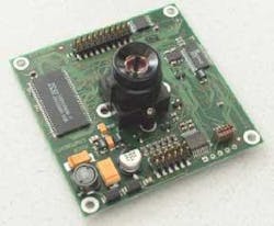
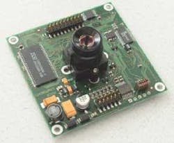
The advent of digital cameras allowed rapid transmission of image data directly to increasingly powerful PCs. Most recently, "smart cameras" provide complete vision systems in a single box (see Fig. 1). Smart cameras are especially popular for applications that require a minimum of customization, and cost less than an image processor card alone did only a few years ago.
Light requirements
Precision vision systems require cameras with high magnification. These optics must have shallow depths of field and short working distances, as well as high contrast and high illumination. This requirement is often complicated by the need to image multiple views of the target. Taken together, the result is a need for the best possible lighting.
In practice, the configuration of the manufacturing equipment or large opaque sections of the target assembly usually makes the ideal lighting configuration impossible to implement. By default, the target is often lit from above using a ring or a line of lights. This configuration can provide uniform illumination that is free of shadows, with the target in the center.
Through-the-lens lighting is an alternative configuration often used when the target is exceptionally reflective or uneven. This makes the most efficient use of light power and directs it where the camera is focused. For either configuration, the most common light sources are halogen lamps or LEDs, although fluorescent and other types of lighting are also in wide use. Fiberoptic cable is also commonly used to route light in tight working spaces.
Regulated power supplies are a must, for although vision software always includes equalization capability to correct for variations in illumination, target identification works best at constant light levels. Illumination must also anticipate and compensate for changes in the lighting environment—what is known as the "white-shirt phenomenon." This refers to the failure of a machine-vision system to perform when managers wearing white shirts gather around it to witness a demonstration.
An edge in intelligence
A fundamental requirement of intelligent vision is to find an edge or border on the target. From this point, the system can proceed to locate and define target features. If the edge is not mechanically registered beforehand, it must be found repeatedly and with great accuracy. Of course, the target must be in focus to allow this to happen.
Finding the initial focus for edge detection can present difficulties. The depth of field is quite shallow for the high-numerical-aperture lenses common to most of these systems, and even small focus errors will result in the image of the edge blurring across multiple pixels. No amount of contrast can compensate for this.
This problem can be resolved using concepts related to the way humans identify objects. Shape-based edge-finding algorithms take advantage of what is assumed about the geometry of the target beforehand. Pattern-matching software then defines the relationship between multiple edges of the target, and uses only these relationships to create a one-dimensional projection of a region of interest.
The software is then capable of using this projection to compute the edge of the target area. It does not need to consider intensities, texture, or background. This technique is capable of quickly locating identical features on different targets despite differences in lighting and orientation. To further ease the focusing task, dual magnification is often used.
The system locates a target feature at low magnification and then defines a registration point for high magnification. The two images can be captured using separate cameras, each with fixed magnification, and calibration software to relate the two image positions. Another technique divides the light throughput of a common input lens to two precisely located cameras with separate magnifications.
Determining system accuracy starts by dividing the area of the field of view (FOV) by the number of pixels. For a FOV area of one square inch and a 512 × 512-pixel CCD, for example, this is about 0.002 inches. The rule of thumb is that to resolve one dimension of a feature, the vision system must see across two pixels, which makes the accuracy calculation for the 512 × 512-pixel camera 0.004 in.
Resolution and speed
To resolve whether a feature is 0.0040 in. wide, and not, say, 0.0036 in., requires a tenfold improvement in this measurement. Resolution depends on magnification and pixel size, and systems that need high magnification tend to rely on sensor arrays with small pixels. Vision software can improve significantly on these physical parameters using interpolation algorithms referred to as "subpixeling."
The advantages claimed for CMOS over traditional CCD sensor technology are generating interest for some machine-vision applications. While its lower power consumption is not usually an advantage on the factory floor, the lower cost of CMOS is attractive. More significant is the advantage produced in image readout speed by the integration of amplification, ADC, and other electronics with CMOS pixel array on a single chip.
A typical readout rate for a medium-sized gray-scale CCD camera is 60 Hz. While this is adequate for many machine-vision applications, 100% inspection on a chip production line requires higher speeds. Vision systems used for identifying pads in wire-bonding operations must locate hundreds of sites per minute.
"Stage motion used to be the limiting factor for throughput," says Terry Guy, product marketing manager for the Kodak (Rochester, NY) Image Sensor Solutions group. As the time to move wafers from station to station has decreased, inspection time has become an increasing concern. By optimizing readout circuitry, Kodak's new KAI-0340 machine vision sensor is able to achieve frame transfer rates as high as 210 Hz to specifically address this bottleneck.
Different visions
Machine-vision technology is about a $5 billion market, roughly divided among 100,000 systems sold per year. The high-end market is the semiconductor industry, which accounts for about one-third of all sales. Other important markets include automotive, medical, and the lumber industry.
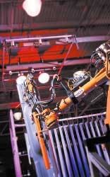
DaimlerChrysler uses multiple In-Sight smart cameras from Cognex (Natick, MA) to meet a 15-second goal at one stage in the assembly of truck beds. The vision systems communicate the coordinates of the large panels to their robotic handlers via an Ethernet link and guide them to their final placement with a 3-mm tolerance (see Fig. 2). Attempts to perform this task by hand had been deemed dangerous to worker safety.
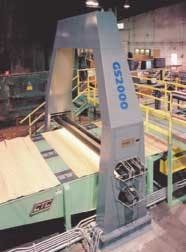
The Ventek (Eugene, OR) GS2000 is used to scan veneer sheets used to make plywood (see Fig. 3). It captures and processes the images that make up a single 4 × 8-ft sheet in 0.5 seconds or less, relying on its neural network software to identify knots, stains, and other defects. Rules must be flexible, as features vary greatly between samples and lower grade veneer sheets can be used in the central layers of the plywood.
The Automated Cellular Imaging System from Chromavision (San Juan Capistrano, CA) uses three-color CCD cameras to automate slide-based testing for pathology. At 60 frames per second, the cameras capture several thousand microscopic images per slide to determine whether cells have absorbed a dye that indicates the presence of disease. If the software detects a diseased cell, the system produces more images at higher magnification.
Machine-vision systems can carry out inspection tasks faster and more accurately than humans. Their measurements are not subjective, they work around the clock, and they can withstand harsh environments. Whether born of the medical industry's need to reduce liability, or from the drive of consumer electronics to lower costs, 100% part inspection using machine vision is becoming the standard.


