Complex designs demand optical engineering code

Complex designs demand optical engineering code
From automotive headlamps to zoom lenses, traditional lens design codes fall short when modeling both imaging and nonimaging aspects of complex optical systems.
Kevin Garcia
Geometrical lens design and analysis have changed dramatically in the past few years to meet the requirements of nonclassical optical systems. A subset of the optical engineering process, lens design has been almost exclusively associated with the design of classical imaging optical systems modeled with geometrical rays, such as cameras, microscopes, and telescopes. Automated lens design programs can efficiently find solutions for a number of classical lens systems. These methods, however, can be restrictive for simulating more-general and more-complex optical system geometries involving nonsequential light propagation and other optical phenomena such as transmitted, reflected, scattered, diffracted, and polarized light. Now, optical engineering software is available to analyze optical systems containing complicated extended sources with a large number of rays; for these applications, automated optimization techniques based on conventional lens design code are inadequate.
Comprehensive optical engineering software has a wide range of uses and can reduce design-to-market time by simulating the design integrity without the need for repetitive and costly prototyping. Applications in virtually every market--automotive, aerospace, entertainment, environmental, illumination, semiconductor fabrication, and telecommunications--span the electromagnetic spectrum from millimeter waves to x-rays. Traditional applications include optical design, image analysis, and performance analysis such as tolerance, sensitivity, ghost-image analysis, and stray-light analysis of imaging system components including camera zoom lenses, microscopes, and telescopes. Nontraditional uses include general optical design and performance analyses of illumination systems such as automotive lighting (headlamps, tail lamps and light pipes in digital displays), general luminaires (street lights, traffic lanterns, and interior lights), back-lighting systems for liquid-crystal display (LCD) screens, and brightness-enhancing films. Many applications include mixtures of imaging and illumination systems such as overhead projectors and LCD projector systems or may go beyond those listed here, as in the case of waveguide design and analysis.
Imaging versus nonimaging systems
Optical systems conveniently fall into two wide classes--imaging and nonimaging. Imaging optics involve computing the first-order properties, aberrations, and radiometry of what typically are referred to as classical optical systems. Nonimaging optics engineering also involves computing the first-order properties, but primarily focuses on the radio metry or photometry of illumination systems.
An optical system can contain both imaging and nonimaging components. For example, a projector system consists of an illumination system, which supplies the light to an object, slide, or LCD, and a classical lens system, which images the object to a viewing screen. Any general optical engineering software should be able to simulate individual imaging and nonimaging systems as well as their potentially complex interactions. The package has to have powerful simulation tools that can be grouped into the following general areas: optical system modeling, source modeling, ray tracing, analysis, and user interface.
Modeling systems and sources
Optical system modeling is of key importance. Because of the complexity of optical systems, it may be necessary to accurately simulate both geometric aspects of the optical elements and mechanical elements. One should also be prepared to model geometries as traditional polynomial entities, solids, or parametric entities that might be transferred from a computer-aided design (CAD) system, because CAD systems are commonly part of the basic engineering data base.
In addition to optical and mechanical modeling, depending upon the complexity of the model, it may be necessary to simulate the indices of refraction of the optical elements, optical coatings, and scattering surfaces that might affect optical system performance. In modeling the Gemini telescope, for example, coatings and scattering models were applied not only to the optical elements, but also the mechanical ones in order to assess the contribution of scattered light to telescope performance (see Fig. 1). Light from stellar objects or man-made sources of radiation may scatter appreciably to sensitive measurement instruments, creating unacceptable system noise.
Source modeling is of equal importance--the greater the degree of source-model fidelity, the less the chance of simulation error. The physical extent of the source greatly influences its behavior in the optical system. Some optical systems can be modeled with point sources, but many require extended sources made up of many point sources. In either case, the source is simulated by a mathematical abstract called rays. The wavefront is a mathematical surface over which the optical path length or optical distance from source is a constant. At every point on the surface, the rays are perpendicular to the wavefront.
Although a point source could be used to examine imaging behavior in imaging optics, it is of less use in simulating the propagation of light in nonimaging optics. For example, an LCD projection system model, which has an arc source, is best modeled with an extended source (see Fig. 2). The physical, spatial, and angular properties of the source, in addition to the characteristics of the illumination system, determine the uniformity of illumination at the LCD plane and thus the uniformity of the screen image. In addition to modeling the extent of the source, its physical properties--wavelength dependence (polychromaticity), apodization, polarization, and coherency--must also be addressed.
Ray tracing and analysis
Having sophisticated optical system models and sources is of little use if the radiation through the optical system cannot be quantitatively propagated. Nonsequential ray-tracing capabilities are required; in addition to the ability to split rays into reflected, refracted, diffracted, and scattered components, optical engineering software must be able to track the ray flux quantitatively. Light pipe modeling, for an automotive display for instance, demands more complexity than lens design codes could provide in the past. An optical engineering software package, such as Advanced System Analysis Program (ASAP) from Breault Research Organization (Tucson, AZ) can model automotive light-pipe systems (see Fig. 3). A nonsequential ray trace is desired to propagate the radiation through the somewhat arbitrary geometry. Ray splitting, with a Fresnel coefficient computation to simulate the reflected and transmitted components, is necessary to properly track the resulting ray flux propagating to the target area.
Once the radiation traverses the optical system, it is necessary to analyze it in terms of irradiance (flux/unit area), intensity (flux/solid angle) or radiance (flux/unit area/solid angle), depending upon the system`s performance requirements. The output might require further image processing as well--for example, irradiance maps of coherent wave propagation through a set of distances.
An efficient user interface can facilitate the use of the software. However, the total package still needs the power and flexibility afforded by a computational engine with a macro language able to be extended to the performance required for current and future complex, sophisticated analyses. Users should avoid being seduced by the illusion of a software product with a race-car body and a lawn-mower engine. Regardless of software sophistication, it is still up to the user to determine what is of importance in modeling a particular optical system. o
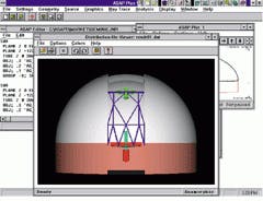
Figure 1. To analyze the design of the Gemini telescope, scattering and coating models were applied to its mechanical parts, such as the dome, as well as the optical systems.
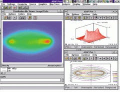
Figure 2. For this extended-source LCD projection system, software must model physical, spatial, and angular properties of the light source, in addition to the illumination system characteristics.
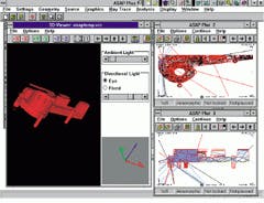
Figure 3. Software simulation of a light pipe for automotive displays shows little light reaching the output planes, identifying unacceptable performance before prototyping.