Modern equation solvers facilitate complex optical-device design
Modern equation solvers facilitate complex optical-device design
Pierre Brosens and Craig Wyatt
Whether having to do with optics, heat transfer, magnetism, electricity, or combinations of these, many design computational problems consist of large sets of nonlinear equations that must be solved simultaneously. Of the mathematical modeling tools available to tackle such problems, TK Solver (Universal Technical Systems, Rockford, IL) is one of the longest-lived, having been around in one version or another since 1982. Release 3 of the Windows version of the program began shipping this past spring, to be followed by Windows 95 and NT versions later in the year. The current version offers versatility for design of state-of-the-art optical and other complex systems (see Fig. 1).
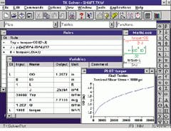
The software package, into which equations and values can be easily inserted, has been widely used to solve engineering and scientific problems. The program fills the gap between spreadsheets and high-end industry-specific software. In the spreadsheet format, the user has access to other program commands. A TK Solver user enters equations, or "rules," on a Rules Sheet, copying directly from a textbook, if need be, without having to isolate variables. All the variables in the rules are posted automatically to a separate Variables Sheet. Inputs are then entered into the Variables Sheet, and the program solves the problem. Problems can be backsolved--specifying desired characteristics and solving for the device parameters that produce those results. Input and output values can be changed instantly, facilitating optimization iterations (see Fig. 2).
The software also can call routines compiled in Fortran and C and make them backsolvable. Using object linking and embedding (OLE), results from TK Solver can be linked to documents created in other applications, such as Microsoft Word. With OLE Automation, developers can create models with custom front-ends using such tools as Visual Basic. Release 3, combined with a new site-licensing plan that permits unlimited software and TK-Solver-based models distribution, offers greater freedom in circulating knowledge bases and applications among workgroups at a customer facility.
Scanner design
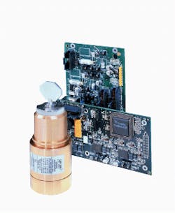
General Scanning Inc. (Watertown, MA), a manufacturer of optical scanning devices for the precise application of laser energy, has saved many design hours with the software package. One example of optimizing laser-scanning design is dynamic-random-access-memory (DRAM) chip fabrication for personal computers. In DRAM manufacture it is necessary to cut selected conductive paths out of thousands located within an area of a few thousandths of an inch, without damage to their neighbors. The laser scanners used in this process consist essentially of a magnetic driver, an attached mirror, a capacitive position detector, and a closed-loop driver amplifier.
About 20 nonlinear equations are involved in analyzing a typical scanner design, not including those required to compute the inertia of moving elements. For highest response speed, the magnetic driver must use a low-inertia rotor, which tends to limit the size of drive coils and raise the power applied to them. The designer`s problem is to develop required magnetic-driver configurations for which it is possible to predict coil temperature when driving a specified inertial load. The model includes a set of equations relating the strength of the drive-coil conductor`s magnetic field as a function of magnetic-material properties, magnet size, and air gap. Also included in the model are equations to relate coil-wire size, drive current, torque produced, coil internal heat generation, and coil peak temperature as a function of the heat-sinking path provided.
Extensive drift calculations
To maximize signal-to-noise levels, the capacitive detector is driven by a high-frequency onboard oscillator, with local demodulation of output via diodes. These diodes have current-voltage characteristics that drift with temperature. Another source of thermal drift is the expansion of the various elements chosen for the sensing electrodes. With proper selection of circuitry, these effects will nearly cancel each other.
The computations required to verify drift cancellation involve about 28 equations that must be solved for each of about 2500 incremental steps of the oscillator cycle. This process results in the proper current and voltage characteristics of each diode being used for the calculation of the integral of the output signal. The calculations are repeated for as many values of rotor position and temperature as desired.
Finally, because the rotor and its mirror exhibit a torsional resonance, it is also desirable to calculate the angular response of the mirror when driven by different types of servo amplifiers. Typically the dynamic elements of a servo circuit, the back electromotive-force (EMF) effects of the coil, and the mechanical load are characterized by a set of 11 to 15 simultaneous linear differential equations.
This extensive analysis represents only some of the physical phenomena to be accounted for in the design of high-accuracy scanners. Some computations could be carried out with a spreadsheet, but this is not practical for computations involving both thousands of integration steps and simultaneous differential equations. Using TK Solver and a 150-MHz Pentium PC, the first two driver-drift problems noted above are solved in one or two seconds. In the second problem, one set of 2500 incremental solutions takes 15 seconds. Solving 11 simultaneous differential equations repeated for 250 time increments takes 100 seconds.
Solutions are presented on sheets showing the range of variables explored and resulting graphs for variables of interest (see Fig. 3). An added advantage is easy handling of the diversity of common units for magnetic fields, currents, background EMF, capacitance, heat transfer, torques, inertias, and mechanical dimensions with automatic conversion to a consistent system of units.
The software allows modeling and quick solution of hundreds of design variations, minimizing the need to construct device prototypes, thus compressing time to market and saving many hours of engineering time. o
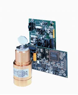
FIGURE 1. Design of systems such as a laser-scanning galvanometer and its signal processor and driver amplifier circuitry requires solution of 20 simultaneous nonlinear equations and thousands of integration steps.
FIGURE 2. Screen features of TK Solver (clockwise from upper left) include a rules window for design boundary conditions and limits, MathLook for displaying characteristic equations, a plot screen, and a window for variable definition.
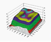
FIGURE 3.
Mathematical construct
of a complex three-dimensional "camelback" function plot serves as a test problem in finding multiple local extremes or multiple roots of simultaneous equation sets typical of high-level engineering design. The plot contains six maxima, two minima, and seven saddle points. Units on horizontal axes refer to data-table references; vertical axis is nondimensional.


