Geometric search finds patterns in changing conditions
Without the advent of machine vision to automate precision assembly and inspection in manufacturing, the world might not have such everyday appliances as personal computers, cellular phones, or home video games. For without this essential automation tool, integrated-circuit manufacturers simply would not have been able to achieve the economies of scale necessary to bring these once space-age ideas to affordable reality.
Machine-vision tools have evolved as demands were placed upon them by the semiconductor-design and manufacturing industry. Driving forces behind this evolution have been the semiconductor industry´s ever-shrinking geometries and the need for more flexibility and reliability under changing process conditions. In the past two years, machine-vision-equipment suppliers have answered this call with a new class of vision tools based on geometric searching principles that provide greater adaptability and robustness than older systems under nonideal operating conditions.
Within the semiconductor- and electronics-manufacturing industries, machine-vision tools are most commonly used to precisely guide robotic-alignment and inspection processes. Wafer handlers, mounters, die and wire bonders, and adhesive dispensers all need to precisely align or register objects such as semiconductor wafers or dies so that operations such as lithography can be performed to extremely tight tolerances. The task for machine vision is to determine the position of the object in the field of view to within 1 µm in the x and y directions and determine angular orientation to within 0.1°.
The tool that is most important for this task is gray-scale pattern recognition. A camera takes an image of the object of interest, such as a semiconductor to be placed on a printed-circuit board as it is moved into position by a conveyor belt or a robot. A computer processing the image assigns each pixel a gray-scale value from 0 to 255, compares the resulting map of values to a preprogrammed reference pattern, and then produces a correlation score based on the percentage of pixels that match the values of the template.
Changed appearances
The most significant challenge for machine vision in these applications is locating reference patterns despite changes in appearance of the material. Such changes are caused by the normal variations in processing. For example, wafers can show nonlinear variation in contrast, such as contrast reversal caused by a chemical-washing process, specular reflection, or shadows from features on the chip that fall differently depending on the angle of incident lighting. Debris can partially obscure a pattern. With objects being viewed on a micron scale, slight variations in placement of the object or focus of the lens cause blurring or alterations of feature size and scale. The orientation of the object relative to the camera can be altered by something as simple as mechanical vibration. To deliver accurate positional data to the alignment and registration process, pattern-recognition tools must be able to adapt to these phenomena.
null
The first step in setting up any pattern-recognition process is to train the system on the pattern or model of interest. Unfortunately, the shortcoming of the normalized gray-scale correlation tools found in most commercial packages is that once they are trained on a particular pattern, they cannot cope with changes in appearance to the pattern at run time. While adequate for locating patterns under ideal conditions, they exhibit low tolerance to image changes in scale, angle, blur, obliteration, and contrast variation. Also, the correlation score resulting from the pattern-recognition process is the sole indicator of confidence.
Unfortunately, correlation scores are sensitive to degraded images. Different parts of an image can have the same gray-scale rating, so correlation tools can give a high score even when their target looks nothing like the template. Pixels that come close to the desired value may be treated as a match in such a way that the combined values add up to a high score even when no real match exists.
An adaptive approach
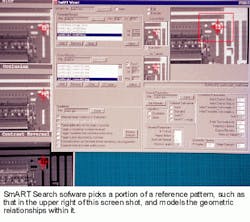
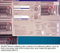
To cope with these difficulties, an adaptive-pattern-finding tool, such as SmART Search from Imaging Technology Inc. (Bedford, MA), is required. It locates patterns with precision 15 times greater than normalized gray-scale correlation and maintains accuracy up to 1/60 pixel, despite degraded images. Instead of being correlation-based, this software is geometry-based. Using an algorithm called GeoSearch, the software locates patterns based on geometric relationships within an image. For instance, it might find a T-shaped feature and measure the width and length of the lines and the angle at which they intersect (see figure). Variations in contrast that confound a correlation-based tool do not affect these relationships, and a change in scale will not change the ratio of, say, line A to line B.
The software provides a score that reflects how well the pattern it has found matches the template it was given. It reports changes in angle, contrast variance, and percentage of conformance to the template. Correlation-based software might, for instance, find that each pixel it views comes close to the value it is seeking and add those measurements together for a score of 75. Our company´s tool, on the other hand, finding perfect matches for 75% of the pixels, would report a 100% match for 75% of the object, leading the user to interpret that part of the pattern was obscured by debris.
The software includes a training wizard that uses artificial-intelligence techniques to optimize run-time parameters. When the user gives the software a pattern to work with, the computer asks a variety of questions. The algorithm then generates simulated images based on this input and performs a test search based on the conditions provided. This enables the user to train the vision system on any location or pattern while the software automatically computes optimal run-time parameters.

