Lens-design programs serve both novice and expert
The process of designing a lens is part art, part science, and plenty of patience. The designer who finds pleasure in the act of designing may well succeed, while the one who loses interest early settles on a lower-quality lens design. Although the lens designers of 50 and more years ago had an endurance that remains unmatched, the invention of the computer and the development of sophisticated software have enhanced the talent of today's designers. They have also opened the door to novice analyzers of optical systems. Today's technology allows the user to trace millions of rays and seek out design solutions faster than ever before.
While there are differences in the details, the fundamental concepts behind most optical-design-software packages are the same. The programs typically have a user interface (either a graphical user interface or a command-based interface), a ray-trace and analysis section, an optimization section, a tolerancing analysis section, and some sort of customized programming section.
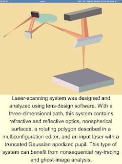
The user interface enables the designer to enter and edit the different aspects of a lens system. Although a simple lens might be all that a novice designer requires, current lens-design software allows the user to describe far-more-complicated systems. Lens systems can contain aspheric, diffractive, and nonrotationally symmetric surfaces, as well as gradient-index materials. While the interfaces from 15 years ago were largely command-based systems, most modern programs use a graphical user interface with a spreadsheet system for data entry. The designer also has the ability to enter multiple-configuration systems, making the analysis of zoom lenses, scanning systems, and variable focus systems easier.
Analysis, from basic to complex
Once a lens system has been entered into the computer, paraxial rays are traced to determine the first-order properties of the system. These are the properties describing the focal length, image distance, numerical aperture, magnification, and pupil sizes and locations. It is sometimes useful at this point to perform an analysis of the third-order aberrations of the lens system, which gives the designer a preliminary idea of whether or not the chosen lens form will have a chance of meeting its specifications.
Software packages today incorporate many of the standard methods of analysis that have been used for decades. The traditional ways of describing the image quality of a lens include transverse-ray aberration plots, through-focus spot diagrams, field-curvature plots, and distortion plots.
With the aid of numerical integration and fast Fourier transforms (FFTs), a host of additional tools for analysis are available. The modulation transfer function (MTF) describes the relative image contrast as a function of increasing spatial resolution. Software programs provide many types of MTF analysis, including MTF as a function of field position, MTF through focus, and diffraction-based MTF.
The point-spread functions show the effect of aberrations and diffraction on the energy distribution of a point-source image. For example, this can be very useful in analyzing the focus of a Gaussian laser beam. The incident light can be described with a Gaussian apodization and can be truncated. The FFT of this distribution is calculated to show an accurate point-spread function.
Wavefront analysis is also available that allows the user to see a three-dimensional plot of the wavefront deviation across the pupil. Wavefront analysis is useful in comparing lenses that work at different numerical apertures.
There are various other software tools that allow for the analysis of partial coherence, polarization, Fresnel lenses, nonsequential surfaces, and ghost-image reflections.
Optimization a vital tool
The most important and time-saving addition to lens-design programs has been the optimization routine, in which the user can create an error function describing the qualities of the optical system. This function is multidimensional and can include information about first-order properties, spot size, MTF, and almost anything the user can think of. The typical error function is where A is the aberration or property to be optimized and W is a weighting factor. There can be hundreds of properties that are included in the error function. The user also can define properties of the optical system that are allowed to vary (for example, radii, element thickness, glass type, and air spaces). The system can then be optimized by changing the variables and minimizing the error function. Most design programs have a default error function that minimizes the spot size across the field.
Because the optimization of the error function will find a local minimum of the function, it is up to the designer to bring the lens to a suitable quality before optimization so that the local minimum is close to a global minimum. In other words, do not expect to place five plano windows of arbitrarily chosen glass in the lens formula and have the program find an optimum solution.
There have been recent advances in the development of global optimization techniques, and most of the major programs claim to have some implementation of them. Although global optimization can be a useful tool in the lens-designer's toolbox, it will not satisfy the designer's wish to "push the button and out pops a lens." In general, global optimization can produce numerous starting points from which the designer can locally optimize.
Tolerancing
The performance of a lens will vary from the nominal design due to manufacturing tolerances. The tolerancing routines of the software provide two key features. By computing the sensitivities of the lens variables, the designer can see quickly which element surfaces and which dimensions will require tight tolerances. It can be very costly to tolerance a lens thickness to ±10 µm when it is in reality insensitive to changes of 100 µm.
The second key feature is a statistical Monte Carlo analysis of the system. This describes to the designer the distribution of the image quality over some number of lens samples.
Customized programming
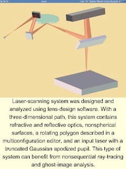
The higher-end software packages allow a designer to program custom routines for further analysis. This can be useful for analyzing a detail specific to a certain project that is not of wide-enough application to be included in the program's base code. It also allows for customization of plots and the way in which data are displayed. The designer can often modify pre-existing macros and so does not have to be an expert programmer to write these routines. With the aid of these macro languages, the possibilities of analysis, optimization, and display of data are virtually endless. The complexity of today's optical systems often necessitates the use of these macros for design and analysis (see figure above).
Optical design, rich in calculations, is an ideal application for computers. The software developed has taken advantage of this. The software has also kept pace with the rapid advancements in the microelectronics and computer industries. What the designer can do-as well as how fast-has changed dramatically in the past decade. There are many different levels of software sophistication and price from which the user can choose to fit his or her needs.
JOSHUA COBB is a senior research scientist at Eastman Kodak Co., 343 State St., Rochester, NY 14650, and coauthor of Light Action! Amazing Experiments with Optics; e-mail: [email protected].


