Optical analysis software automates ghost busting
Optical analysis software automates ghost busting
Gary Peterson
In an ideal world, lenses and windows would transmit all of the light incident on them without loss, scatter, or reflection. But in practice, transmissive optical components always reflect a small amount of the incident light. These unwanted reflections are known as ghosts. When they propagate to the focal plane or detector, they become a source of stray light that can interfere with the performance of an optical system. In high-power laser systems, ghosts can cause damage. A ghost focus that is located within or near an optical element can generate enough heat to damage delicate coatings; a stray ghost beam can damage sensitive detectors, including human eyes, in any surrounding diagnostic systems. For these reasons it is important to identify and fix ghosts early in the design process.
A ghost analysis must answer several important questions: What elements generate ghosts? Where do the ghosts go and where do they focus? How much power or irradiance do they contribute to the detector or other area of interest? Is the ghost power or irradiance more than can be tolerated? And finally, how can ghosts that are causing trouble be reduced or eliminated?
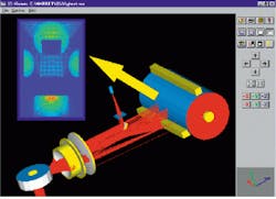
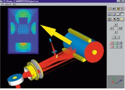
Not so long ago, answering these questions was a laborious task that involved identifying ghost paths one by one and then tracing a few rays for each path to find the location of a focus and perhaps calculate the power or irradiance at the detector. But nonsequential ray-trace software has automated this process. Commercially available optical-analysis packages can identify and track hundreds or even thousands of ghosts without direct user interaction, assess their magnitude, sort out those that are most troublesome, identify the specific optical elements that cause them, and test the effectiveness of design changes that reduce or eliminate them (see figure).
Doing the real work
Solving ghost problems with software begins with construction of a computer model of the optical system geometry. In some software packages these models can be imported directly from an optical design program or even a computer-aided-design system. Once the optical geometry is constructed, additional information on the system can be entered that is relevant to the ghost analysis.
This might include a coating prescription for the lenses and windows, locations and dimensions of mechanical apertures or stops, or transmission or reflection properties of beamsplitters, filters, or reflective mechanical components.
When the computer model is finished the real work begins with a comprehensive ray trace through the system. Software tracing of numerous rays through a system allows the job to be done in a reasonable time and provides the user with a sense of confidence that all of the significant ghosts have been found. As rays are traced through the model, additional ghost rays are split off at each surface of a lens or window. Ray-tracing software not only follows the paths of these rays through the system, but also assigns and tracks the flux of both parent and ghost rays. It can even take into account the variation in transmitted or reflected flux with angle of incidence.
Frequently, ghost rays will generate additional ghost rays of their own, second- and higher-order ghosts, until all rays either reach the detector (or other area of interest) or are absorbed by the surrounding mechanical structure. Optical-analysis software sorts and tabulates all of the rays on the detector, based on their history. It then displays a table showing which objects generated ghost rays and how much power each ghost contributed to the detector.
Irradiance calculations can also be performed at the detector to determine the magnitude and distribution of the ghost light. These calculations are compared against stray-light specifications to determine if a change is needed in the optical design. In scanner systems it may be necessary to do several ghost runs to account for different orientations of the scan wheel.
Fixing the problem
If the ghosts are too large, the next question is what to do about them. One solution is to apply antireflection coatings to the lenses or to improve existing coatings. A quantitative ghost analysis helps here. When the magnitude of the ghost power and irradiance are known, coating specifications can be written that are not too tight, a waste of money, or too loose to solve the problem. In fact, if the analysis shows that only one or two surfaces are responsible for the ghost problem, then some of the lenses may not need new coatings at all, resulting in additional savings in the manufacturing process.
If changing the coatings is insufficient or impractical, there are additional measures that reduce ghosts. For example, if the problem is caused by a focused ghost from a single element, then a change in the lens prescription sometimes helps. Subject to imaging requirements, the radii of curvature on an offending lens can be adjusted to move the ghost focus in front of or beyond the sensitive surface. Once again, optical software is helpful here. First the elements causing the problem are identified, so no time is wasted fixing elements that are not a problem. Second, the effectiveness and magnitude of any changes are determined in software without the need for a hardware prototype.
If the problem ghosts come from a window or flat lens surface, then adding a small tilt or wedge may move the ghosts away from the detector. It should be noted that a single ghost reflection from an element is strongly affected by tilting the element. But if the stray light comes from a double reflection from the front and back of the element, then tilting it does not change the ghost direction. This is because the tilt on the front and back surfaces of the elements compensate for each other. In this case a wedge is needed to move the second order ghost.
If a problem ghost moves outside the volume occupied by the desired light then it is sometimes possible to insert a baffle to intercept it. Graphical ray traces can show if such a baffle is effective and determine where to place it.
Identifying ghost problems in advance of hardware implementation, locating the source of problems, and testing the effectiveness of possible solutions are all assisted by the advent of modern optical-analysis software. No longer is it necessary to guess at the sources of problems or their solutions. Reliable and rapid assessment of ghosts can now be made in the earliest stages of a design, when inexpensive changes can be made on paper, as opposed to expensive changes later on in the hardware. o
Ghost calculation as it might appear on commercially available software shows three-dimensional model of a laser printer in which light propagates from a laser diode and is redirected by a flat mirror toward a focusing lens and scanner wheel. In this design, the same lens is used to collimate the light before reflection from the scanner wheel and to focus the light on the drum. Ghost rays that are reflected from the lens elements propagate to the drum. Inset color ma¥shows an irradiance calculation over a plane surface in front of the drum. Inspection of a ghost-path table and irradiance distribution quickly show whether ghost reflections are a problem or not. (Image courtesy Breault Research Organization)

