TERAHERTZ OPTICS: Wire-waveguide simulation matches experiment
Waveguides that carry terahertz radiation can be vastly different from conventional optical waveguides. A simple metal wire will do; the wire carries the radiation as surface-plasmon polaritons that penetrate only tens of nanometers into the metal while extending millimeters to centimeters (depending on the frequency) into the surrounding air. Dispersion increases as the wire diameter goes down, and the surface properties of the wire affect both dispersion and absorption.
Researchers at Rice University (Houston, TX) and the University of Technology Delft (Delft, The Netherlands) are characterizing such waveguides, in simulations and in experiments. Their latest efforts concentrate on what happens to terahertz radiation at the end of a wire waveguide.1 The researchers have determined that frequency-dependent diffraction at the wire’s end causes the near- and intermediate-field electromagnetic distributions to be frequency-dependent. The results are important for understanding how best to use such waveguides.
In one experiment, terahertz pulses are coupled to a stainless-steel wire with a 1 mm diameter via a sharp copper tip, which scatters the pulse onto the wire by creating the proper surface-wave modes. A 1-mm-thick electro-optic zinc telluride crystal near the end of the wire elliptically polarizes a synchronized probe pulse by an amount proportional to the field strength. In another experiment with a 0.9-mm-diameter wire, terahertz pulses are coupled into the wire via a perpendicular wire 0.5 mm away. In this case, a fiber-coupled photoconductive emitter and detector generate and detect the terahertz pulses; spatial resolution is 6 mm.
Two experiments agree
In the first experiment, measurements for a transverse displacement of the probe from the wire axis of 2 mm, and for varying axial distances from the wire, show a shift of the spectral maximum from 0.11 to 0.2 THz for corresponding axial displacements of 0 to 4.24 mm. The second experiment, with its more-sensitive probe setup, shows a shift from 0.2 to 0.35 THz for axial distances from 1 to 45 mm. As different as they are, both experiments show very similar results.
Simulations were then done using the Multiphysics software package, a commercially available finite-element physics modeling program from Comsol (Burlington, MA). The waveguide model, which is discretized into 1.5 million mesh elements, is based on a metal wire 0.9 mm in diameter and 2.5 cm long, with a time-varying electric field applied to one of the wire ends; calculations are done a single frequency at a time. The model is 3-D, rather than radially symmetric. (The computer workstation, which has dual 64-bit processors and 16 MByte of RAM, takes about three hours to arrive at a solution.)
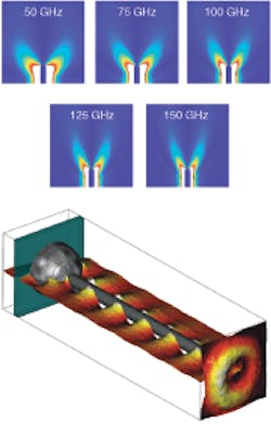
The simulations indeed show that the intensity distribution varies with frequency (see figure). The intensity at the wire axis is zero because the mode is radially polarized. Future time-domain-based (as opposed to frequency-domain-based) modeling will help the researchers understand more details, such as end-face reflectivity.
REFERENCE
1. J.A. Deibel et al., Optics Express 14(19) (Sept. 18, 2006).
About the Author

John Wallace
Senior Technical Editor (1998-2022)
John Wallace was with Laser Focus World for nearly 25 years, retiring in late June 2022. He obtained a bachelor's degree in mechanical engineering and physics at Rutgers University and a master's in optical engineering at the University of Rochester. Before becoming an editor, John worked as an engineer at RCA, Exxon, Eastman Kodak, and GCA Corporation.