Illumination Optical-design Software: Illumination-design software optimizes complex geometries
Classical optical lens-design software has grown vastly more capable over the years, but when an optical engineer needs to design nonimaging systems (such as illuminators) rather than imaging systems, there’s nothing better than dedicated illumination optical-design software to do the job. Such software (which can be a standalone application or a module of a standard lens-design package) is intended for designing light pipes, lens arrays, diffusers, light sources, standard optics, and combinations of all these, all with highly asymmetrical configurations if needed, and producing customized illumination intensities and patterns if desired. The following is a sampling of various types of illumination-design programs on the market.
Dedicated application
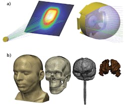
One example of a dedicated illumination-design application is LightTools by Synopsys (Mountain View, CA). According to Stuart David, group director of applications engineering in Synopsys’ Optical Solutions Group, LightTools supports virtual prototyping, simulation, optimization, and photorealistic renderings of precision illumination applications (see Fig. 1). “It directly represents optical entities such as sources, receivers, light pipes, reflectors, lenses, diffusers, prisms, diffractive elements, and beamsplitters in the same model and environment as mechanical components and structures,” says David. “The software has incorporated solid-modeling technology to accommodate the inherent accuracy required to simulate ray paths of light as they traverse among and within optical elements and mechanical structures.”
Applications include backlit displays, lighting and luminaires, LED-based sources, light pipes and light guides, augmented, mixed, and virtual reality (AR/MR/VR), medical, vehicle lighting, lidar and remote sensing, and others. “LightTools recently introduced the Tolerance Manager, which helps designers predict the manufacturability of their illumination systems and control manufacturing costs,” notes David. “The feature is particularly useful for illumination systems that require precision manufacturing, such as LED-based light guides, lidar, and freeform illumination components.” The Tolerance Manager provides insights early in the design process into potential problem areas and can also be used to analyze systems already in production.
LightTools can be used in conjunction with other Synopsys tools, such as Simpleware (see Fig. 1), to provide simulation data to develop a new generation of light-based technologies, including advanced biomedical diagnostics and treatments, and wearables for augmented reality, says David.
“Simpleware software provides a solution for 3D image data (MRI, CT) visualization, analysis, and model generation for export to CAD, CAE, and 3D printing,” explains Kerim Genc, business development manager of Synopsys’ Simpleware Group. “Together, Simpleware and LightTools can enable real-world optical scenarios to be accurately reproduced in simulation, using detailed models of human anatomy. R&D simulations for medical devices, as well as for consumer products and electronics which optically irradiate the human body, can be achieved through this software partnership.”
Integrated package
An example of illumination design found in the same package as imaging-optics design is found in OpticStudio by Zemax (Kirkland, WA). Katsumoto Ikeda, principal optical engineer at Zemax, notes that OpticStudio has both sequential and nonsequential modes: in sequential mode, all ray propagation occurs through surfaces, which are located using a local coordinate system, while in nonsequential mode, optical components are modeled as true three-dimensional objects, either as surfaces or solid volumes. Each object is placed globally at an independent x, y, z coordinate with an independently defined orientation.
“For illumination design specifically, the software’s nonsequential mode provides an extremely flexible alternative to the restrictions of sequential ray tracing, and helps engineers perform the complex modeling required for many illumination applications,” says Ikeda. “For example, a light-bulb filament or the emission region of an LED are types of designs that are not well modeled by simple point sources. Both direct rays and those that get reflected by surrounding structures contribute to the overall illumination provided by the source. This can be particularly complicated when using so-called ‘white LEDs,’ where the blue light is provided by the LED emission and the redder spectral components are provided by a much larger fluorescent re-emitter surrounding it. Both components are reflecting, refracting, and scattering in different ways. Balancing these to make uniform light requires consideration of nonsequential rays, especially if the application has tight specifications.”
Light-pipe propagation is especially complex this way, explains Ikeda, because the “surface” of the optic is really a tube that can bend into a very complex shape, and light can bounce many times off the inside before it exits. “The nonsequential ray tracing capabilities of OpticStudio do not suffer from the same limitations that sequential ray tracing does. Since rays can propagate through the optical components in any order, total internal reflection (TIR) ray paths can be accounted for,” he adds.
In one example given by Ikeda of an OpticStudio design, a fly’s-eye lens intended for uniformizing the spectral and spatial output of a white LED is selected for a homogeneity solution.
Then, careful placing of the lenslet array and optimization of the lens prescription is performed using the software’s nonsequential analysis tools (see Fig. 2). The result of the optical design is analyzed with a color detector in OpticStudio to show the result as if the human eye viewed the illumination pattern. The detector mimics the photopic response of the human eye, making it particularly useful for white-light illumination system design requiring knowledge of the photometric (human eye) response of the system to a broadband source. The resulting illumination is both homogeneous in color, giving a white effect, and also delivers optimal illuminance as a uniform distribution.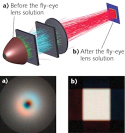
CAD-based approach
Due to their very nature, computer-aided design (CAD) programs provide 3D modeling capabilities, so why not use CAD as a basis for the inherently complex 3D optical modeling needed for illumination design? This is what Lambda Research (Littleton, MA) has done with TracePro, which is a 3D solid-modeling-based optical analysis program built around an industry-standard CAD kernel. “This allows for the ability to model illumination systems directly in TracePro, as well as excellent file exchange and interoperability with CAD programs,” says Dave Jacobsen, senior application engineer at Lambda.
Ray traces can be done using the software’s Monte Carlo-based engine, while properties such as surface and material properties can be applied to the model either from the included property database or using custom properties added by the user. There are several methods for modeling the light sources such as rayfiles and source properties in TracePro, says Jacobsen. After tracing the rays, TracePro can show the user numerous analysis plots such as illumination patterns, candela or intensity distributions, luminance values, and photorealistic or lit appearance displays. Parameters such as geometry, properties, and light sources can be varied and changed and the resulting performance evaluated—IES and LDT files can then be generated and saved for use in architectural lighting programs.
TracePro’s Interactive Optimizer uses the Nelder-Mead, also called downhill simplex, method to allow the software to search through the space of possible solutions to try to find the best design to meet the goal, automating the optimization process, notes Jacobsen. It also allows users to define optimization targets or goals that are relevant for illumination tasks, such as uniformity, illumination pattern, beam pattern, flux values, color coordinates, and so on. The tool is used for design of illumination, automotive lighting, displays, backlighting, and other lighting applications.
In one example, the goal was to optimize a total-internal-reflection (TIR) hybrid lens (see Fig. 3). As described by Jacobsen, the original lens had been designed and optimized manually by changing the shape of the lens in the software, running a ray trace, looking at the results, and then making another change, and repeating the process. This optimization took two to three days to get to an acceptable design. “Using the existing design as a starting point, we used the Interactive Optimizer in TracePro to see if the design could be improved,” says Jacobsen. “Whereas the initial optimization took several days, this new optimization took less than one hour. The result was a 1.5x gain in intensity from the newly optimized lens."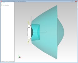
Optics plus multiphysics
Multiphysics modeling allows one to not only design and optimize an optical system, but to then model thermal and other effects on the optics and optomechanics. This approach, taken by COMSOL (Burlington, MA), takes the form of the COMSOL Ray Optics Module, which is an add-on to the COMSOL Multiphysics simulation software. “Rays can be traced through homogeneous or graded-index media, and at boundaries they can be absorbed, refracted, or diffusely or specularly reflected,” explains Christopher Boucher, technical product manager at COMSOL. “Ray tracing is suitable for analyzing a wide range of illumination and imaging systems such as cameras, telescopes, optical filters, spectrometers, and laser focusing systems.”
The software can be used for every step of the modeling and simulation process, including geometry setup, definition of physics, numerical analysis, and results processing and export, says Boucher. The geometry can be created from scratch or loaded from a variety of third-party CAD packages.
“For a high-fidelity optical simulation, it is often necessary to consider all of the physical phenomena that affect the optical system, Boucher says. “For example, temperature changes can cause refractive indices to change. Furthermore, thermal stresses, applied loads, and gravity can deform the geometry. The COMSOL software makes it easy to combine all of the physics into a single, comprehensive model. Field variables like temperature and structural deformation are solved using the robust finite element method (FEM), and then the solutions are passed to the ray-tracing simulation. The entire workflow is seamless.”
An example given by Boucher of Multiphysics simulation of an optical system (although in this case not an illumination system) is the gravitational analysis of a telescope (see Fig. 4). The image shows a Newtonian telescope at an angle of 45° from the ground. First, the stresses and strains of the telescope due to gravity are computed using FEM, and then rays are traced so that they reflect off the primary and secondary mirrors in the deformed geometry. Even these small deformations can have a significant effect on the image quality.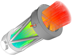
Often, it is of interest to look at variations of the same model, with different inputs, to find an alternative design, says Boucher. The gravitational analysis of the Newtonian telescope could be extended, for example, by executing a “parametric sweep” that automatically reruns the analysis on a telescope with different input parameters, such as geometric dimensions, different material properties, or by orienting the telescope at different angles.
Light-source models based on real data
A 3D nonsequential Monte Carlo ray tracer optimized for nonimaging optical design called Photopia, produced by LTI Optics (Westminster, CO), bases its light-source models on real source geometry, material, and spectral emission properties measured in a custom-built, high-dynamic-range (HDR) imaging-based device. Photopia is used for a range of applications such as illumination, irradiation, signaling, optical sensors, and light pipes, says Mark Jongewaard, the company’s president (see Fig. 5). The software package includes a stand-alone program and an add-in that works fully inside of SolidWorks, a well-known 3D CAD program.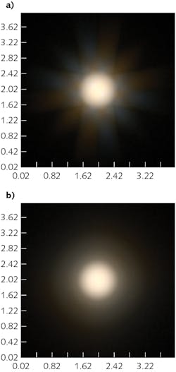
“Illumination optical design often requires strict control of light distributions, ranging from an automotive headlight with specific cutoff requirements to an LED wall washer that needs to provide a smooth distribution free of any striations or color variations,” says Jongewaard, adding that Photopia’s library of measured light-source models and materials ensures accurate input data. “Photopia’s light-source models are based on real source geometry, material, and spectral emission properties, including spectral changes across area and angle,” he explains. “Photopia’s reflective and transmissive materials use bidirectional scattering distribution function (BSDF) data [measured by the earlier-mentioned HDR device]. Having real measured input data with geometry is preferred to other software that may rely heavily on the use of ‘ray sets,’ since they can lack key aspects of the source properties, including their variable spectral details and accurate emission points.”
In architectural lighting, “white tunable,” “circadian,” and “human-centric” products are popular categories that often include both warm and cool white LEDs to allow for changing spectral output depending on the time of day. The optic is typically responsible for mixing the output from multiple LEDs uniformly while also shaping the light into the desired pattern.
“The push for smaller optics with more-precise beams means the optical designer needs to be able to determine just how much color mixing is required to blend without widening the beam too much,” says Jongewaard. “Photopia includes a range of parametric optical-design tools to allow designers to iterate over optical shapes quickly to optimize rial library also allows the designer to evaluate adding specific levels of micro-etching to certain surfaces to scatter and blend the light. Since the task is to blend two spectrums into a uniform beam, having accurate LED source models with full spectral properties is required to fully verify the design.”
Modeling of architectural spaces
While the software mentioned up to this point relates to illumination optics themselves, designers that use these illumination systems in architectural spaces need to be able to model the effects of lighting in the environments they were intended for, such as rooms and building exteriors. DIALux, software produced by DIAL (Lüdenscheid, Germany), simulates and visualizes the distribution of light based on photometric measurements of light sources and luminaires. As described by Marc Allefeld, product owner for DIALux, the software takes the light distribution of a luminaire and spectral data for light color into account using calculations based on a “photon shooter” approach, and compares and evaluates the results against standards. DIALux uses isolux curves, which helps to evaluate the distribution of illuminance values on various surfaces (see Fig. 6).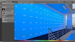
“With DIALux, one can do an evaluation of quality of light in terms of visual appearance and the fulfillment of standards,” says Allefeld. “A typical use case is that of a lighting designer who wants to evaluate the illuminance values on different surfaces inside a room, such as walls, ceilings, or table surfaces. It brings a calculation approach for light and photometric data based on measurements together.”
When designing a new optic or reflector, it is possible to simulate and visualize the effect of light for that new design, explains Allefeld. The designer imports the photometric data via an IES file, runs a calculation, and evaluates results and the visual appearance of the modeled light, thus getting an impression of the product as it will be used in reality.
For More Information
Companies mentioned in this article include:
COMSOL
Burlington, MA
DIAL
Lüdenscheid, Germany
Lambda Research
Littleton, MA
LTI Optics
Westminster, CO
Synopsys
Mountain View, CA
Zemax
Kirkland, WA
DISCLAIMER: While we try to include information from the broadest possible number of companies that manufacture the products featured in our Photonics Products series, because of limited word count as well as deadlines that cannot always be met by requested contributors, we cannot possibly include all companies and regret if your company is not included in our series.
About the Author

John Wallace
Senior Technical Editor (1998-2022)
John Wallace was with Laser Focus World for nearly 25 years, retiring in late June 2022. He obtained a bachelor's degree in mechanical engineering and physics at Rutgers University and a master's in optical engineering at the University of Rochester. Before becoming an editor, John worked as an engineer at RCA, Exxon, Eastman Kodak, and GCA Corporation.