Closed-loop control enables precise nanopositioning
Extremely high resolution and accuracy, high stability, and quick response are the desired properties of a nanopositioner, but conventional motion-control technologies are unable to meet such requirements. New techniques are being developed, however, to build systems that provide nanometer-level position control combined with high-speed motion.
Scanning probe microscopes (SPMs) offer high-resolution imaging but do not provide metrology capability. The most common SPM scanner is a piezoceramic actuator, which is nonlinear and subject to hysteresis, resulting in displacement errors. These errors increase with increasing scan length. Software correction techniques are often used to remove these errors, but to achieve positioning accuracy to the nanometer-level closed-loop feedback is required. Closed-loop feedback involves sensing the actual position of the stage (scanner) and correcting it to achieve the desired location.
Custom closed-loop feedback stages can be designed for specific applications and incorporated into metrology instruments. So, in addition to extending the metrology capability of scanning probe instruments such as atomic-force microscopes, scanning tunneling microscopes, and near-field scanning optical microscopes, potential applications also include nanopositioning devices for fiberoptic alignment and laser tuning.1
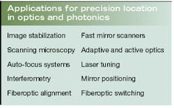
Nano location means knowing a relative position within 1 nm (10 Å), less than the diameter of a water molecule. In microscopy, the ability to sense the position of a scanning probe with nanometer precision enables an SPM to render measurements of surface characteristics as an accurate topographic map. Such ultraprecise motion control is essential in a wide variety of optical and photonic applications (see table, above).
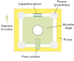
The key to position sensing is a capacitance-based three-dimensional (3-D) position monitor that provides accurate feedback to the controller to correct positioning errors.2 Pure linear motion with minimal parasitic errors is achieved with flexure-guided moving elements—a scan in the x-axis does not cause motion in the y- or z-axes. The flexures are monolithically cut into the stages using precision electro-discharge machining. When properly designed, the stages have wide dynamic range (a high resonance frequency), millisecond response times, as well as ultrasmooth positioning and true planar motion. The flexure guides, piezoactuators, and sensors form an integral stage system (see Fig. 1).
Flexure hinges
The nanopositioner consists of a movable component inside a rigid frame. The motion can be controlled in any or all of three translational axes, as well as in angular axes such as rotation or tilt. Displacements are smooth and continuous, rather than discrete, and all degrees of freedom can be achieved with the same precision. By adhering to stringent design criteria, the flexures are able to produce predictable and repeatable motions at the atomic level.
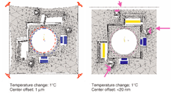
Positioners are conventionally mounted at four fixed points, which can lead to frame distortion and motion due to thermal expansion and the force applied by the piezoactuators (see Fig. 2). By mounting the flexure hinges in a three-point kinematic mounting system, however, contact coupling and friction in the system can be avoided. Systems designed in this manner are compliant in the decoupling direction and very stiff in all the other directions, maintaining the center position of the moving platform of the stage.
Flexure hinges can also combine nano-level motion within longer-range motion. The precision is maintained as the same percentage of the motion as in the nanopositioner. For example, a positioner with 10-cm range of motion and 1-µm resolution has the same precision as a nanopositioner with 100 µm of motion and 1-nm resolution. Separate sensor systems provide the transition from coarse motion to nanomotion for this combined long-range and nanometer motion, The combination of flexure hinge mounting and position sensing reduces the out-of-plane motion to less than 5 nm over a 100-µm scan distance. Scanners driven by tubular piezo elements actually scan along a curved path and will go out of plane by thousands of nanometers over a 100-µm scan.
Capacitance sensors
Piezoelectric actuators create the force required to produce the motion of the moving part of the positioner, and only piezoelectric materials are capable of reliably producing motion and position with subnanometer resolution. These materials change dimension when a voltage is applied, and although this change is quite small (typically 0.1% of the total length), large forces are generated. The dimensional change is generally proportional to the applied voltage, but piezoelectric materials and actuators are nonlinear and exhibit hysteresis. So an external sensor is required to monitor the true position of the movable part of the positioner.
High-efficiency piezoelectric actuators can generate a greater expansion for a given applied voltage compared to the most commonly used piezos having the same dimensions. The use of short, high-expansion piezos facilitates the design of stages that are more compact and thus achieve higher resonant frequencies—and therefore higher speeds—while maintaining maximum travel. Properly designed flexure stages can have resonant frequencies as high as 5 kHz.
Because of small differences in the material properties and dimensions, nominally identical piezoelectric actuators respond differently to an applied voltage. Piezo scanners also exhibit more sensitivity at the end of their distance of travel than at the start. The relationship between movement and applied voltage is nonlinear, causing hysteresis between the two scan directions. These differences are corrected by having the controller operate in conjunction with a capacitance sensor (or capacitance micrometer).
Capacitance micrometers are small, simple, noncontact measuring devices with displacement-resolving power that is theoretically in the subangstrom range. Attaining this level of precision is inherently difficult, however. Limits are primarily due to noise in electronics and to changes in the dielectric between the plates and require ultralow-noise electronics.
Controller technology using ultralow- noise circuitry design and advanced algorithms is required to effect motion control at the nano level. As additional control and intelligence features are added, digital signal processing technology is being added to speed response and reduce noise. Positioning noise, which correlates with positioning precision, can be as low as 0.5 nm in the x-y direction (with 100 × 100-µm range) and 0.1 nm in the z-direction (with 20 µm).
Custom or off-the-shelf?
The diverse range of optical applications is such that more often that not a catalog part will not do the job. Nanopositioner manufacturers cannot foresee all of the possible applications and cannot afford to offer off-the-shelf designs for every contingency. An alternate approach is to outsource the design engineering. Scanners can be custom designed to OEM and R&D requirements. Although nanopositioning technology can provide the capability to see and manipulate at regions down to the atomic level, specific expertise is required to build systems that operate at extreme levels of precision and speed.
Conventional structural metals such as aluminum, stainless steel, and Invar, for example, can be replaced with novel materials better suited to the application. Electron-beam lithography, for instance, requires nonmetallic and nonmagnetic materials. To improve scanning speeds well beyond current levels, lighter, composite materials are being explored for flexure pattern designs that can minimize the distortion of the frame and maximize the resonant frequency.
YING XU is vice president and chief technical officer of nPoint, 1617 Sherman Ave., Madison, WI 53704; e-mail: [email protected].
REFERENCES
- K. Moloni, R&D Mag. 44(1), A11 (January 2002).
- Y. Xu et al., Proc. American Soc. for Prec. Engin.14, 20 (1996).


