Automation improves optical system performance
Automation improves optical system performance
Lawrence C. West
Most optical engineers and scientists have some motion-control elements in their laboratories, but these devices are usually limited to tasks such as scanning or positioning a mirror or grating. Systemwide automation can greatly improve the precision and quality of laboratory experiments while saving time and lowering equipment costs. Computer-controlled mirrors in a high-performance laser, for example, can maintain optimum system output power and beam quality; the benefits of enhanced performance alone can often justify the cost of the automation system.
AutoOptics (Integrated Photonic Systems; Clarksburg, NJ) is an automation system designed for optical laboratories. It can perform tasks such as motion control, switching, and signal interfacing with a set of simple commands that can be grouped to perform complex tasks across an entire system. To align detector
B using motor A, for example, the command is "Align(B,A)". The controller connects detector B to the appropriate chopped-signal amplifier or dc input and sets the gain, time constant, and other parameters; then it connects the motor, performs a scan, optimizes detector position, and stores the position for future reference. The same command can be applied to any combination of detectors and motors in sequence for rapid systemwide alignment.
Automatic control
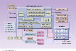
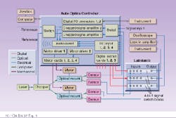
The power of an integrated automation system expands with multiple-element systems. The AutoOptics unit provides control signals for motors, analog and digital signal interfacing, and a digital interface to LabMatrix, a subsystem designed for laboratory signal switching. A typical setup features the controller driven by a computer interface and integrated with as many as 32 motors attached to optical components, gratings, or a laser (see Fig. 1). The computer provides user-level control, while the controller performs only the lower-level interface tasks such as driving the motors or counting encoder pulses.
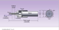
The motor assemblies, delivering up to 42 in.-oz of torque, fit nondestructively into existing mounts from various suppliers. They consist of four interchangeable parts: the motor itself with gear reducer and encoder, a front flange with three index pins, a screw of chosen diameter and length, and a housing (see Fig. 2). After motor installation, the user configures the software by entering the dimension and pitch of the screw to define the movement achieved by one rotation--this can be translated into linear or rotational motion with various units.
The encoder provides 64 counts/rotation, combined with either a 262:1 or 485:1 gear reduction. For the standard 0.5-mm pitch screw, this corresponds to a resolution of 0.03 or 0.016 µm, respectively. Manufacturing variations in the screw thread and motion stage tolerances often limit positioning accuracy to several times these figures, but with the elimination of hysteresis, the relative accuracy of the units is sufficient for such applications as beam scanning or cavity length adjustments.
The system operates through a Windows interface with messages, buttons, and indicators that can change form depending on the task. The software includes a script interpreter for the simplest automation programming. For more-complex operations, the system can be used with LabView control software (National Instruments; Austin, TX) or programmed in C or C++ using C-based library functions.
In addition to automation, the system provides useful features for manual alignment, including exponentially varying motor control, AudioAssist for audio monitoring of mechanical adjustments, and computer display of motor positions and signal levels.
Switching and configuring
Most laboratories today still switch their signal connection by disconnecting and reconnecting their cables manually, like a 1940s switchboard operator. The LabMatrix unit integrates electronic instrumentation into the AutoOptics control system, automatically connecting instruments such as oscilloscopes to optical devices such as detectors or modulators (see Fig. 3). LabMatrix also extends the number of analog signal connections to the main controller
The software can store a selection of system configurations, each with a unique name, multiple states of motor position and signal selection, and a floating-point parameter such as wavelength, temperature, or power. Users select the motor and signal elements belonging to the configuration set, and the software saves the current parameter values selected for each element.
For example, a system can be set up for angular scanning through a pinhole using mirrors and a rotation stage. The user aligns the beam to the pinhole for five to ten angles, optimizing the throughput on multiple axes for each angle, then storing the configuration for each one using the angle as the defining parameter. When a given angle is reselected, the controller restores the configuration. If the angle specified is not one of the stored values, the controller linearly interpolates motor positions between the two stored configurations with parameters closest to that angle.
Aligning, scanning, and stabilizing
The alignment command controls one or two motors at a time based on the output of a single sensor. The system automatically connects the detector with the same settings as used previously and performs the alignment by making simple scans in each direction, within a range specified by the user.
This technique is fast and robust even in the presence of noise, with only one or two scans in each direction generally required to perform the task. If two motors are selected, then the system performs either an alternating alignment or a two-dimensional raster scan. The alternating sequential alignment has the advantage of quickly acquiring signals. The raster scan performs a complete two-dimensional search in the event of total signal loss. The approach can also aid in finding a non-local maximum, for example, in a beam-walking (position and angle) laser-alignment process.
Although conventional scanning options are available for everything from spectrometers to laser gratings, they are generally expensive and poorly integrated. AutoOptics allows users to automate scanning as part of the laboratory process. By attaching a motor to a monochromator knob, for example, an engineer can use the controller to automatically scan a system and acquire data on output power as a function of wavelength, plotting the data with user-defined parameters and saving them for export into a plotting routine or word processor.
Saving time
Most engineers know the location for optimum application of motion control--it is the knob that they frequently adjust to improve system performance. The controller can, in effect, replace the knob by automatically adjusting system parameters such as beam power to stabilize performance over short-term or long-term periods of data acquisition. Optimization with the controller typically requires less than 10 s per axis. If drift is slow compared to experiment time, a rapid realignment just before data acquisition may be sufficient. For longer experiments in which system parameters drift during the data-acquisition process, stabilization involves moving the motor by a small increment during the experiment and checking for improvement on the alignment sensor.
Integrated laboratory automation provides time and cost savings while enhancing the precision and quality of laboratory experiments. The lack of high-quality, economical, and useful systems has slowed progress toward optical laboratory automation, but AutoOptics offers a flexible, simple, and fully integrated move in that direction. o
FIGURE 1. Automation system consists of AutoOptics controller unit with computer interface, up to 32 external motors, and the LabMatrix electronic instrumentation control unit.
FIGURE 2. Direct current motors fitted with driving screws can provide u¥to 42 in.-o¥of torque. For available gear ratios and a standard 0.5-mm pitch screw, this corresponds to a resolution of 0.03 or 0.016 µm
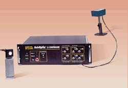
FIGURE 3. AutoOptics laboratory automation system controls mounts, instrumentation, sources, and detectors to enhance optical system performance.


