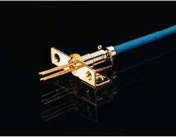
Optoelectronic components must fit in tiny packages
Optoelectronic components must fit in tiny packages
Matching micron-sized tolerances, maximizing coupling efficiencies, and minimizing retroflections are essential to successful optoelectronic package design.
Jan Lipson
An optoelectronic module must correctly accommodate the thermal, mechanical, electrical, and optical requirements of the devices being packaged--and the optoelectronics package design must also address two distinct differences from typical electronics packaging. First, in the packaging of semiconductor lasers at least one element in the optical chain must be aligned to submicron or micron tolerances. And, except in the case of expanded-mode lasers, at least one element must maintain its radial position to submicron tolerances over the life of the module.
Second, the design must accommodate appropriate optical elements for coupling a sufficient amount of light into the system fiber (whether directly into a fiber or to a receptacle that will later receive a connectorized fiber). These additional criteria result in many additional packaging constraints on the choice of materials and configurations.
Semiconductor lasers are normally encapsulated in a clean, hermetic environment. The devices may be packaged in a small container, such as a sealed TO header, or the laser may reside in a large rectangular package with a sealed lid. Detectors may be treated similarly, although in some cases a hermetic environment is unnecessary. Rectangular packages and headers are usually made with Kovar alloy because its expansion coefficient matches that of glass- or ceramic-based electrical feedthroughs.
The base of a rectangular package usually must have greater thermal conductivity than Kovar. Typical choices are copper/tungsten or copper/molybdenum/copper, which are coexpansive with Kovar. Laser submounts must be coexpansive with indium phosphide or gallium arsenide and must have good thermal conductivity. Typical choices are aluminum nitride, silicon carbide, silicon, or diamond. Laser-weldable materials must be relatively free of impurities that are sometimes introduced to improve machineability. Typical choices are Kovar and 304 stainless steel.
Packages may come with fiber pigtails or receptacles that are designed to receive connectorized jumpers. The specification of a connector type is usually made based on a trade-off between cost and the reflectivity of the connection. In applications where reflections must be avoided, angled connectors are generally used. Rectangular packages are typically provided in a butterfly or DI¥format. When this type of package contains a laser, a thermoelectric (TE) cooler is usually added to kee¥the laser at constant temperature. Header-based packages are cylindrically symmetrical. If no further enclosure is used, these modules are not cooled.
Optical design considerations
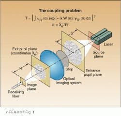
Correct prediction of the coupling efficiency between a semiconductor laser and single-mode fiber requires use of a model that accounts for aberrations of the lens system, although a more intuitive understanding can be obtained by consideration of unaberrated Gaussian beams.1,2 In a typical setu¥the optical system images the laser into the fiber with appropriate magnification, and a sto¥is included to define the spatial limits of the optical collection system (see Fig. 1).
For all the classical aberrations, approximately 0.3 wave is sufficient to cause 1-dB loss in the system. The beam divergence from typical semiconductor lasers is very wide so it is hard to find lenses that will maintain less than 0.3 wave over a large fraction of the far-field. Specially designed aspherical lenses usually come closest to producing optimal results.
When no aberrations are present, any loss of coupling is due to a mismatch of the imaged far-field and the fiber far-field. Usually the divergence angle of these beams differs by a factor of four, hence the optimal magnification is approximately four. Laser beams, however, are also elliptical, whereas the fiber far-field is circular. Unless corrected by nonaxi-symmetric optics some loss invariably results. For ellipticities of less than 1.5, the loss is confined to 0.4 dB. Typical radial tolerances for fiber alignment are about 2.2 µm for 1 dB of loss. If the lens is integral to the fiber, those tolerances must be divided by the magnification giving rise to submicron sensitivity. Hence, packages in which a discrete lens is used are superior to those in terms of process tolerances.3
Arranging optical systems to prevent optical reflections is one of the most challenging aspects of optical design. Two forms of degradation can be observed. Feedback into the laser cavity can cause critical properties to become unstable. Furthermore, the formation of Fabry-Perot cavities in the package will provide a wavelength-sensitive transmission function. As the laser frequency varies with current, the transfer function gives rise to nonlinearities in the laser output. For analog video applications, these cavities must be suppressed. The most sensitive applications are those in which a distributed-feedback laser is operated continuous-wave and the linewidth is critical. In such instances, feedback to the laser should be limited to less than -80 dB.
In most high-performance applications, reflections from connectors and the fiber itself are important. In these instances an optical isolator must be used. An inherent property of such isolators is that they can be optimized only for a single temperature. Isolation deteriorates substantially at temperature extremes. If the laser is kept at constant temperature by a TE cooler, the isolator can be placed on the cooler as well.
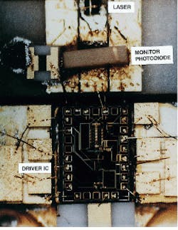
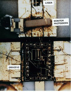
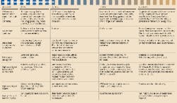
The requirements and consequent design of optoelectronic modules differs drastically for different applications (see table). In a 10-Gbit/s transmitter, the driver must be kept close to the laser. A well-controlled 50- transmission line leads to the driver (see photo on frontis). A typical return-path package is similar to those in construction of modules used for digital transmission at low to moderate bit rates (see Fig. 2).
Increased optical isolation is needed if no signal is present for the return-path laser. The absence of chir¥increases the coherence and causes the laser to become unstable due to feedback from Rayleigh scattering in the fiber. Furthermore, the carrier-to-noise ratio degrades substantially at low frequencies due to double Rayleigh backscattering. These problems can be greatly alleviated if a low-frequency dither signal is always present.
Package reliability
Qualification of terrestrial optoelectronic components is primarily governed by Bellcore Standards TR-NWT-000468 and TR-NWT-000983, which deal separately with outside-plant applications. One should note the central role that temperature cycling plays in package qualification. Our experience at Ortel (Alhambra, CA) has been that design weaknesses that will affect field failure rates are usually revealed best by this test. By contrast, aging experiments are often unenlightening.
In the best-designed devices, critical joints that are determinants of the alignment are formed using high-temperature materials. Laser welding and the use of gold/tin solder to bond lasers and submounts are typical examples.5 In these cases, the plastic regimes occur at temperatures much higher than the operating temperature. Projections of device stability using a thermally activated model for stress relief--such as Arrhenius law--are often without merit. It is much more important for users to satisfy themselves that process controls are adequate to make sure such joints are always well made. Rigorous change control methods in these areas can never be omitted.
Another significant cause of failure is fiber breakage. Fibers will break spontaneously if the built-in stresses in the fiber assembly are sufficient. Careless handling can also reduce the strength of the fiber. It is particularly important to avoid abrasion or water infiltration at the surface of bare fiber.
A special case of package-induced laser failure occurs for 980-nm pum¥lasers in which any significant contamination with hydrocarbons could induce early catastrophic failure. In our opinion it is very important that the hermetic enclosure around the laser be bakeable to high temperatures to drive off contaminants. The presence of a fiber pigtail is decidedly disadvantageous in performing such a bake because the buffer and jacket materials outgas in the most desirable regime. It is best, therefore, that the laser be previously encapsulated.
For undersea applications, package qualification is based more on a rigorous analysis of a particular design and its potential failure modes. Superior reliability is achieved not only as a result of the additional rigor, but because the experiments are carefully designed to produce a basis for satisfactory failure modeling.
Trends
In the area of low-cost packaging for loo¥applications, the emergence of beam-expanded lasers may give rise to packages in which no lens is necessary.6 Alignment tolerances are then such that 1-µm-level chip-placement techniques may suffice for coupling. It is not obvious, however, that these methods will result in lower costs than with the current popular coaxial packages. Many vendors are well down the learning curve for these products, and vigorous competition has effectively reduced prices. A move toward nonhermetic detectors and laser modules seems potentially more promising.
The issue of moisture management may be reconsidered in light of superior plastics that are now available and the relatively long diffusion times associated with these materials. The actual amount of water contained in a fairly large package is less than 2.0 mg. If the laser is separately encapsulated this amount of moisture cannot be detrimental, assuming that none is allowed to condense on optical surfaces.
The impedance that the plastic presents to water infiltration prevents a cooler from acting as continuous moisture pump, hence, unless the package is operated for a lengthy period of time in rain-forest-type conditions, little moisture will enter. Nearly all cooled modules operate in central offices or head-ends where typical dew points are far lower than 25C (normal set-point for laser) unless air-conditioning fails. Such failures are typically not allowed to persist indefinitely. Provided due care is taken in the design, we anticipate that such modules will have completely equivalent field reliability to products based on fully hermetic cans.
Another emerging trend is flip-chip-mounted detectors and lasers. This technology generally produces lower electrical parasitics with smaller variances and is very useful for high-speed components.
Design considerations
The overall design of an optoelectronic module is constrained by factors not encountered in typical electronics packaging. Severe restrictions on joining techniques and materials are imposed by the submicron stability required in laser modules. Contradictory criteria may appear such as the need to kee¥the electrical path in high-speed packages electrically continuous but thermally discontinuous. Reflections can degrade device performance and in some cases must be managed to levels below -80 dB.
High reliability requires low-stress fiber assemblies, proper fiber handling, and attachment techniques where stress relief cannot give rise to motion. The latter is achieved with joints whose plastic regime is at very high temperature. Finally, separate encapsulation of the lasers can provide a basis for inexpensive nonhermetic packaging for the rest of the module, while keeping the lasers free of contamination. o
REFERENCES
1. R. W. Wagner and W. J. Tomlinson, Appl. Opt. 21, 2671 (1982).
2. W. B. Joyce and B. C. Deloach, Appl. Opt. 23, 4187 (1984).
3. J. Lipson and R. E. Scotti, in Tech. Dig. OFC `88, OSA/IEEE, New Orleans, paper ThL4 (January 1988).
4. J. Lipson et al., in Proc. SPIE Intl. Symposium on Fiber Optics, Optoelectronics and Laser Applications, Boston, MA, 376 (Sept. 1988).
5. R. S. Moyer et al., in Proc. 38th Electronics Components Conference, EIA, Los Angeles (May 1988).
6. Y. Sakai et al., in Tech. Dig. OFC `96, OSA/ IEEE, San Jose, CA, paper WL9 (Feb. 1996).
Internal view of a 10-Gbit/s transmitter module shows the integral driver circuit and 1.55-µm distributed-feedback laser. This device was developed for the US Defense Advanced Research Projects Agency`s West Program.
FIGURE 1. Integral solves the coupling problem of getting laser output into a single-mode fiber. Generally, the elliptical laser beam must be imaged into the circular fiber. T is the coupling efficiency, and yS` and yR` are the far-field emerging from the image of the source laser and fiber, respectively, as observed in the exit pupil plane. The term in the exponent, W(a), accounts for the wavefront aberrations of the system (adapted from Ref. 1).
FIGURE 2. Coaxial laser module for return-path transmission applications appears similar to packages used for digital transmission at low to moderate bit rates. However, an optical isolator is included in this package.
JAN LIPSON is vice president, advanced development, at Ortel Corp., 2015 West Chestnut St., Alhambra, CA 91803; e-mail: [email protected].
