Chillers and Coolers: Laser chillers evolve to meet industrial and medical space constraints
Higher laser output power in increasingly smaller packages has many benefits in reducing the floor space requirements in production floor, cleanroom, medical operating room, clinics, and laboratory environments. Laser product managers are seeing similar pressure to reduce the size of the external laser chiller while still offering improved cooling and energy efficiency—some are considering adding the refrigeration system directly into their laser system to form an integrated compact package. It is important to make decisions early in the product development cycle to ease integration of advanced cooling methods such as direct refrigerant cooling.
Cooling system choices
The table (see http://bit.ly/2ifXMKI) lists cooling methods used in modern laser systems. Laser efficiency, laser temperature requirement, heat load, heat flux at the device, ambient air temperature, and facility infrastructure are determining factors in choosing a cooling system design.
For systems with low heat output and/or relatively high allowable temperature limits, above-ambient systems normally provide sufficient cooling. For systems with more stringent temperature requirements where fans and pumped liquid loop systems are not adequate, then either vapor compression (VC) or thermoelectric (TE) systems are used to manage laser temperatures. Both TE and VC systems draw power to enhance the heat transfer from the laser to ambient air, and enable cooling levels and heat fluxes not possible with passive means.
Multiple studies by U.S. government agencies have examined cooling technologies for efficiency and effectiveness in a variety of applications. A 2010 study sponsored by the Department of Energy compared VC systems with five competing technologies, including thermoacoustic, TE, and magnetic technologies, emphasizing efficiency and determining that VC systems are at least 3X more efficient than all other current options.1 An earlier study conducted by the Environmental Protection Agency concluded that "vapor compression refrigeration using non-CFC refrigerants is the most desirable technology of those considered for use in the five application areas: domestic, commercial, and mobile air conditioning; and commercial and domestic refrigeration."2 The results rank vapor compression cooling first in the technical assessment of each of the above-mentioned methods, as it uses 3-5X less power than TE cooling systems.
Thermoelectric coolers
Thermoelectric coolers (TECs) use the Peltier effect, where a heat flux is generated at a junction of two dissimilar materials, across which a DC electric current is passed. TECs are constructed with p- and n-type semiconductors that are arranged parallel in the thermal path and in series along the electrical path (see Fig. 1).
When a voltage is applied across the device, electrons carry heat to one side, making the other side cold. As the heat load rises, the amount of current required to maintain the correct temperature also must go up since the flow of electrical current is necessary to carry the additional heat load. As a result, the efficiency of TEC devices is quite low.
As with all cooling systems, the heat removed from the device must be dissipated to the ultimate heat sink, normally to ambient air with a fan. Typical coefficient of performance (cooling power divided by power draw) for a TEC device is in the 0.5-0.2 range, meaning that to provide 400 W of cooling, the TEC would need to draw between 800 and 2000 W of power.
Thermoelectric coolers can be fabricated in a variety of configurations and made into small sizes for low-power applications, as well as provide precise temperature control. Other than the fans and pumps to which they are often attached, TECs have no moving parts—so they require minimal service. The TEC assembly can be mounted directly onto the laser cold plate or used to chill a flowing liquid. Because of its low efficiency, TE cooling is typically only used in applications requiring <400 W of cooling.
For applications that require a high level of temperature stability, one consideration is a hybrid approach of using vapor compression for the bulk of the cooling power and a small TEC assembly for a high degree of regulation.
Vapor-compression refrigeration
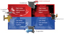
Vapor-compression cycle refrigeration is a process in which the physical properties of a refrigerant are exploited to realize isothermal, two-phase heat transfer to efficiently provide cooling. Heat is absorbed from the source being cooled in the evaporator, where a refrigerant absorbs heat as it is converted from a liquid to a gas (see Fig. 2).The compressor takes in the gas discharge from the evaporator and raises its pressure and temperature. The condenser takes in this superheated gas and condenses it from a gas to a liquid as heat is dissipated to the outside environment. In some cases, the condenser is designed to dissipate heat to a closed-loop liquid line that is part of the manufacturing facility. The expansion valve takes in the high-temperature liquid refrigerant and lowers its pressure and temperature. This low pressure and temperature gas/liquid mixture then flows into the evaporator, repeating the cycle.
The components in a basic refrigeration system are the compressor, condenser, expansion valve, and evaporator. Refrigeration systems efficiently move heat from a cold source to a heat sink. Vapor compression refrigeration systems are very efficient, with a typical coefficient of performance between 1.0 and 2.5. For a 400 W heat load, the power draw would typically be between 400 and 160 W—this is 1600-640 W less than equivalent TEC systems.
By varying the evaporator, the vapor-compression cycle can be used to cool air, liquid, or cold plates. To create an air cooling system, the evaporator is a refrigerant to an air heat exchanger, and to cool liquid, the evaporator is a refrigerant to a liquid heat exchanger, with the pumped liquid being cooled by the evaporating refrigerant.
A third alternative for cold-plate-cooled devices is to run the refrigerant directly through the cold plate. With the evaporator as the cold plate, the devices being cooled have the advantage of phase change heat transfer with minimal temperature rise. Figure 3 shows examples of these three implementations of vapor compression cooling.4Compressor-based liquid chillers are the most widely used cooling technique for high-power lasers. Compressor size can be specified for cooling power from approximately 100 W to >10 kW, and can cool most laser types.
Miniature rotary compressor
In 2007, a small rotary compressor was first introduced and put into communications systems for cooling military electronics.3 The compressor uses standard rolling piston technology that has been miniaturized and coupled with an efficient brushless DC motor. With a speed variability between 2500 and 6500 RPM, the compressor can effectively load match to the desired temperature.
The small compressor enables miniaturization of vapor compression systems into smaller form factors and provides an effective match with heat loads down to 100 W. These small vapor compression systems are now being developed for commercial applications, including lasers, medical devices, electronics, and pharmaceuticals.4
Liquid chillers
Liquid recirculation requires a mechanical pump, reservoir, tubing, and fittings. With the vast improvement of laser reliability, the liquid cooler is seen as the weakest link in the system. Pumps and fittings are known to fail, and leaks around electronics can cause a laser failure. Fluid levels in these systems need to be monitored and occasionally refilled because of evaporation, and it is recommended that an algaecide be used to prevent biofouling of the recirculating liquid line.
Pump selection is critical to ensure proper flow rate and pressure for the intended application, and prices can vary from a few tens of dollars to over $1000, depending on the quality of construction. A common thread heard from laser manufacturers is that an end user, who may have spent $100,000 or more on a laser, will purchase an untested low-cost chiller to save a few hundred dollars. When these chiller systems lose effectiveness or fail, they can cause downtime for the user and warranty issues for the laser supplier.
Another common complaint from laser users is that the chillers are unreliable and difficult to maintain. Although the liquid chiller is the most common approach to cooling lasers, this type of feedback highlights an opportunity for improvement.
Direct refrigerant cooling
A new development being explored by some laser manufacturers is direct expansion cooling. Here, the refrigerant flows directly through the cold plate, with the circulation being driven by the compressor. This method eliminates the need for a liquid recirculating pump, fluid reservoir, and associated tubing and connectors, all of which are sources of failures and leaks.
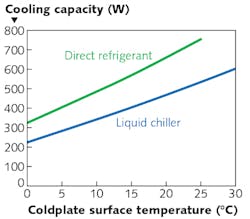
Efficiency is improved by removing the losses associated with cooling a liquid and energy savings of driving a pump (8X less vs. TEC and 2X less vs. liquid chiller). The cooling capacity for direct refrigerant is 25% greater than a liquid chiller at 25°C (see Fig. 4). The system is simplified, improving reliability (MTBF >80,000 hours) and further reducing the size of the cooling system.Three design issues need to be addressed when using direct refrigerant cooling: vibration from the compressor, which may adversely affect the beam pointing stability; a reliable means of decoupling the cooling circuit from the laser for laser or cooling system maintenance without loss of the refrigerant; and attaining sufficient control of the laser temperature tolerances. In a typical direct expansion cooling system, copper tubing is rigidly connected from the compressor to the cold plate, allowing vibration to transmit along these lines. One way of addressing this is the use of flexible refrigerant lines that can decouple the compressor vibration from the laser.
For removing the cooling system from the laser, refrigerant line quick disconnects that are designed to prevent air ingress and refrigerant leakage can be used. These are specifically designed for use in refrigerant lines, and provide an easy means of disconnecting the two lines while maintaining system integrity.
Enhanced control over the laser temperature can be attained by coupling the laser controls directly to the refrigeration system controls. In this manner, any thermal lag in the direct refrigerant system can be overcome by the control system. This degree of controls integration is unnecessary with much larger liquid chiller systems since they often use the fluid reservoir and its innate heat capacity to maintain tight thermal control.
Miniature refrigeration technology is now advanced for effective application to laser systems that require active cooling with high efficiency. These systems are being custom-designed to meet OEM and end-user conditions, producing a wide selection of laser thermal management applications. Applying direct refrigerant cooling further miniaturizes the cooling system, and improves efficiency and reliability.
REFERENCES
1. D. R. Brown, N. Fernandez, J. A. Dirks, and T. B. Stout, "The prospects of alternatives to vapor compression technology for space cooling and food refrigeration applications," Department Of Energy Report No. PNNL-19259, prepared under DE-AC05-76RL01830 (Mar. 2010).
2. D. C. Gauger, N. Shapiro, and M. B. Pate, "Alternative technologies for refrigeration and air-conditioning applications," Research and Development EP/600/SR-95/066 (May 1995).
3. G. Deming, "2U rack mountable vapor compression cooling system for high power electronics," Electronics Cooling (May 2008).
4. J. Burnett, "Advances in vapor compression electronics cooling," Electronics Cooling (Jun. 2014).
About the Author
Rick Slagle
Managing Partner, Technical Solutions Marketing
Rick Slagle is a managing partner at Technical Solutions Marketing (Maynard, MA).


