Bench-design innovations enable high-performance optics
Bench-design innovations enable high-performance optics
The combination of high rigidity and light weight has allowed optical benches with honeycomb structures to replace granite tables in many applications.
Richard Barrett
Vibration control has become an enabling technology for many industrial and scientific applications in which the slightest motion in the working surface distorts test results and reduces process resolution. The list of diverse applications for vibration control includes materials research, laser development, semiconductor-wafer fabrication, fiberoptic-systems production, and microscopy. Important design considerations extend beyond the optical bench itself to environmental parameters as well as the experiment and process layout. The benefits of good design include increased manufacturing throughput, quicker and more reliable data acquisition, and improved system resolution and accuracy. This article focuses on the design of the optical bench and also discusses nontraditional uses of these design techniques.
Control techniques
Effective vibration control requires several steps. The first step is to reduce the system`s exposure to ambient noise. This is usually done by locating the system on the ground floor, away from large machinery and out of immediate air-flow paths. Nearby machinery, including pumps and motors, is isolated on soft mounts, which attenuate rather than transmit vibrations.
The second step is to isolate the electro-optical system by supporting the work surface on soft-coupled mounts. These devices can include passive rubber mounts, springs, or pneumatic isolators. More-demanding environments can use electronically controlled isolators that actively cancel vibrations through a feedback system.
An additional design step for a stable electro-optical setup is to prevent relative deflections of the optical path. Rigid support structures for every optical element in the system allow each element to withstand transmitted vibrations.
Another crucial step is to maximize the rigidity and damping characteristics of the optical support structure. Even when the work surface is isolated, some vibrations will transmit, so the table must be designed to reduce the response to vibrations.
Bench design
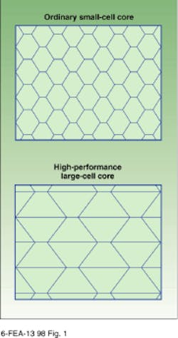
The design goal for an optical bench is rigidity in response to structural deformation imposed by external forces. Traditionally, granite--highly polished to precision flatness and very heavy--was the desired material for a rigid optical bench. While granite provided inertial resistance to motion, it had a poor damping response. Optical benches with honeycomb structures have replaced granite in many applications because they exhibit a better combination of high rigidity and light weight than an equivalent granite table (see Fig. 1). The high stiffness-to-weight ratio of the honeycomb structure shifts the structural resonant frequencies to a higher, less detrimental region.
Honeycomb support structures are usually made from a steel core with laminated steel skins on top and bottom and with lighter-weight side-panel enclosures. For custom applications, the core material can also be made of nonmagnetic stainless steel, aluminum, or other specialty materials. With proper design, structural weight can be reduced without sacrificing rigidity by increasing the size of each honeycomb cell. A bifurcated cell is one such method.
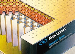
The top skin is usually drilled and tapped for mounting optomechanical components; magnetic steel is common to allow the use of magnetic mounts. The side panels can be made of either steel or composite materials, because they are not required for structural strength--except in unusual edge loading--and are primarily used esthetically to close off the core. When composite materials are used in the side panels, they offer the additional benefit of attenuating rather than enhancing stray vibration.
Vibration damping
Each table, as a function of its materials, size, and thickness, has unique dominant bending and torsional modes, and each of these modes has a characteristic frequency and table-deformation shape. Tuned damping of the resonance modes improves the vibrational stability of an optical bench or table.
The most effective tuned damper design consists of a mass, suspended in viscous damping oil and held in place by a pair of tuned leaf springs (see Fig. 2). The whole assembly is hermetically sealed in a steel case. Multiple dampers can be used with each table, and each damper can be specifically tuned to minimize table motion at a specific resonance mode. When two or more tables are doubled together to make a larger vibration-controlled work surface, the tuned damper design allows the combined tables to be damped as a whole. Using tuned damping and rigid doubler technology allows the tables to act as one structure once reassembled on-site.
Component assembly
Manufacturing the table raises several issues. First, the honeycomb core must be bonded to itself using a rigid epoxy. The core is also bonded to the bottom skin and then to the top. The top surface is pressure-bonded to the core using metrology-quality steel assembly platens. The large platens provide an end-to-end flatness with less than ۪.004-in. variation over a 20-ft-long table. The room-temperature curing process eliminates thermal stresses and further improves dimensional accuracy.
The table usually has tapped holes for mounting electro-optical equipment. Standard practice requires that these holes be sealed from the interior of the table to prevent corrosion from accidental spills of dyes, solvents, water, food, or hazardous chemicals. Among the various methods of sealing these holes, a one-piece layer of fiberglass-reinforced resin works well. The resin resists corrosion as well as mechanical failures and punctures.
Traditional optical tables and breadboards, designed according to the principles described above, are found supporting many manufacturing-grade lasers. For instance, deep-ultraviolet excimer lasers, produced for the semiconductor-lithography market, require a high degree of vibration isolation because they are used to write submicron features on wafers.
Unusual shapes
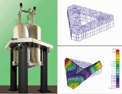
Honeycomb structural designs are not limited to the traditional rectangular shape of an optical bench. The example in Fig. 3 is a support for a cryogenic helium Dewar, containing an atomic force microscope, which also requires vibration-free performance. Researchers at Lawrence Berkeley Laboratory (Berkeley, CA) use a similar setup for the study of two-dimensional electron gases in gallium arsenide structures. The structure was initially modeled using finite-element analysis, and the modeling allowed the design engineers to predetermine the natural frequency modes of the structure and apply the appropriate damping.
Another application for these design principles can be found in the vertical fiber draw towers used in the production of optical fibers. During processing, the fibers are heated and drawn to the proper diameter and properties, and any vibration between the process stages will introduce nonuniformity in the fiber. Newport Corp. (Irvine, CA) has built honeycomb fiberoptic draw towers up to 482 in. (more than 12 m) high. These structures use the same table-design technology and tuned damping found in research-grade optical benches. o
FIGURE 1. Cutaway view of a research-grade table shows sidewalls, top skin, drilled mounting holes, and honeycomb structure.
FIGURE 2. Tuned damping system focuses damping effort on dominant frequencies.
FIGURE 3. Triangular hybrid honeycomb structure for support of the Dewar was developed using a finite element analysis for this system.
RICHARD BARRETT is product line manager for vibration-control products at Newport Corp., 1791 Deere Ave., Irvine, CA 92606; [email protected].


