Aspheres: The impact of shape factor on asphere design
With the development of improved optical manufacturing and metrology methods, aspheric lenses are more common than ever before. With aspheres being widely available, determining which asphere fits your needs is not always a simple answer. It is important to consider the shape factor of an asphere, as well as the conjugate ratio (the ratio of object distance to image distance).
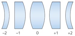
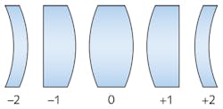
Shape factor is related to the radii of curvature of spherical lenses, so the shape factor for an asphere is a starting place from which optimization can begin. A shape factor of -1 indicates that the planar side of the lens is facing the object (see Fig. 1). Aspheres designed in this configuration are known as “best form” or “planar hyperboloid” aspheres and are optimized to eliminate spherical aberration at one design wavelength. A shape factor of +1 indicates that the convex side of the asphere is facing the object or illumination source at an infinite conjugate. This configuration is designed to minimize the focused spot size and is the same convex-plano configuration typically recommended for spherical optics. This is the shape factor that Edmund Optics uses when designing aspheres and will be referred to as the TechSpec design form for the rest of the article.This article will discuss these two shape factors and the design methods used for each of them. It is assumed that the reader has a basic understanding of optical design when it comes to setting up optimizations. While they are both aspheric lenses, a different approach is necessary for each method. The best form asphere has a closed-form solution, which means there is an explicit best solution to the problem. This makes best form aspheres relatively simple to design, while the TechSpec form is more of an iterative process when it comes to the design. These forms have differences that could lead a customer to choose one instead of the other.
The designs
As stated earlier, best form aspheres are a closed form solution when it comes to design. After determining the necessary radius of curvature, the solution for the shape of the surface is a conic constant that is equal to -1 × n2, where n is the refractive index of the glass.
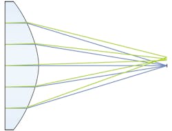
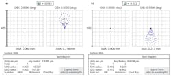
While best form aspheres achieve a diffraction limited spot on-axis, changing the wavelength presents a change in the lens’ index of refraction. This causes the optimal conic constant of the aspheric surface to change, which leads to a dependence of spherical aberration on wavelength. This is known as spherochromatism and results in poor spot-size performance for wavelengths other than the one design wavelength for which the asphere was originally optimized. There are issues when using a -1 configuration off-axis as well (see Fig. 2), as coma becomes overwhelming at angles as small as 0.1°. This design only works with an infinite-conjugate source incident on the planar surface or a point source at the focal distance away from the convex surface.For these reasons, the best form asphere works best when used with lasers, since they are highly monochromatic, collimated sources. However, the flat surface of the asphere reflects incident light directly back to the source, which could be an issue in certain applications. Using an asphere designed for a -1 configuration in a +1 configuration with the collimated source incident on the convex surface will result in poor performance.
The TechSpec design solution is not a closed-form solution, and therefore requires more designer input to get a solution. The presence of two surfaces that are bending light causes the solution to become more complicated. This discussion will involve the use of the even asphere polynomial:
A TechSpec design form starts as a +1 shape factor, which presents issues when designing very low f-number (f/#) lenses. When starting the design for a plano-convex lens, the radius of curvature defines the focal length of the system. As the system approaches an f/# of 1, the curvature of the surface approaches a hemisphere. When this happens, the rays at the edge of the aperture bend at extreme angles. There is a chance that these extreme angles will cause total internal reflection to occur at the planar exit surface, causing the ray-tracing software to produce an error when performing a sequential ray trace. The remedy for this is to add an arbitrary conic, which flattens the rays so their respective incident angles are smaller than the critical angle.
After finding the proper parameters for the required focal length, the aspheric terms of the curved surface should be made variable. Normally, the second- and fourth-order terms are left at “0,” as the second-order term will change the radius of the surface, changing the focal length, and the fourth-order term will be detrimental to the conic constant. For this design form, the fourth-order term can vary, and will not hurt the optimization process. The process is iterative, as a higher order should only be permitted to vary when optimization does not produce a diffraction-limited spot size.
During optimization, it is important to ensure that the design does not develop an inflection point, as this leads to aspheres that are difficult to manufacture. A quick check of the surface-curvature cross section will let you know if you have an inflection point. More information regarding asphere inflection points can be found in the 2012 SPIE journal “Asphere design for dummies.”1There is also a reduction of the off-axis spot size. The improvements to off-axis performance, specifically, are beneficial because slight misalignment of an asphere is equivalent to adding a field point to the system, so TechSpec aspheres are less sensitive to misalignment than best form aspheres. While TechSpec aspheres are suitable for laser use, their benefits are more pronounced with polychromatic sources. Using this lens in reverse will not only lead to worse performance, but it could also cause an issue with total internal reflection.
Can I make this asphere?
Designing the perfect asphere for your application is only useful if the lens can be realistically manufactured. To ensure that the designed lens performs as intended, it must be toleranced so that it can achieve its intended performance with manufacturing tolerances that reflect how it would be actually made. Manufacturability of the lens has to be taken into account since a part that is difficult to manufacture will lead to an increase in cost.
The task of ensuring that an asphere will be manufacturable occurs during the design process. The easiest property to control for this purpose is the edge thickness of the lens. This is important, as the lens blank that is used in manufacturing is oversized, usually by 1 to 2 mm, to ensure that the lens can be properly centered during fabrication. If this oversizing isn’t taken into account and the resultant edge thickness is too small, the element could be prone to chipping because of a sharp edge, or even be impossible to manufacture. The center thickness in the merit function should be controlled so that the edge thickness of the oversized part is on the order of 1 mm. Conversely, making the edge thickness larger will not hurt the lens, but could increase the cost of the part.
An easy mistake to make when designing aspheres is to ignore the significant figures used during design. Just because the display on the lens data editor/manager shows n decimal places, this does not mean that the parameters have been rounded to that decimal place. Make sure to truncate the final design to however many decimal places or significant figures are requested by manufacturing. Not properly truncating significant figures can cause discrepancies between a technician’s sag table and the original design. Firstly, the need for clarification will cost time and money. Secondly, the performance of the asphere could be different if the improperly truncated values are used, causing the need for a redesign.
Tolerancing aspheric lenses is similar to tolerancing spherical lenses, particularly with respect to center thickness, refractive index, and wedge. Meanwhile, the tolerancing process for other specifications (such as radius of curvature, irregularity, and power) is dissimilar to that of spherical lenses. For example, the radius will vary, but is not a function of a test plate and some departure from that test plate, as it is for spherical lenses. Because of the metrological processes used for asphere testing, there is only one necessary tolerance for the change in base radius. In addition, the irregularity specification is replaced by a surface sag deviation, which controls the deviation of the surface sag from the nominal design.
Because of the varying profile of aspheres, subaperture polishing is used to generate the correct shapes. One drawback to subaperture polishing is the fact that ripple can be left behind due to the process. These ripples are known as mid-spatial-frequency errors, and they can have a debilitating effect on element performance. Dealing with this type of error is probably the most difficult portion of the tolerancing model because of limitations in ray-tracing programs. As with all designs, the lower the f/#, the more sensitive the design will be to mid-spatial-frequency errors.
Aspheres can be tailored to fit the particulars of an application. If a custom design is necessary, clear communication with the designer regarding materials, performance, and cost are invaluable. The same goes for the designer when it comes to communicating with the manufacturer. Without knowing the limitations on how an asphere is generated or the metrology used, a lens may be produced that meets the manufacturing requirements, but not the performance requirements. It is hoped that the ability to model mid-spatial frequencies will be included in future versions of common ray-trace programs, helping designers correctly model an asphere to ensure that it is not only manufacturable, but will have a good yield and performance as well.
REFERENCE
1. K. Oka and S. Sparrold, “Asphere design for dummies,” Proc. SPIE, 8487, 84870B (Oct. 19, 2012); doi:10.1117/12.930989.
About the Author
Eduardo Gonzalez
Optical Engineer, Edmund Optics
Eduardo Gonzalez is an optical engineer at Edmund Optics (Barrington, NJ).


