Test and Measurement: MRF fabricates 'perfectly bad' surfaces
The final finishing step in any optical-component manufacturing process has always been associated with improving the surface or wavefront. Magnetorheological finishing (MRF) and its deterministic polishing approach is well known for the benefits it brings to this important step. This approach is, of course, fine when the desired result is a flatter or more spherical (or conventional aspheric) surface, even when such a surface is expected to be λ/10 peak-to-valley or better. What is one to do, however, when simply making the surface flatter or more spherical isn't enough, or when the desired shape is something other than a "perfect" plano or spherical surface?
Certain components and applications require optical surfaces and wavefronts that deviate in a very specific way from the flat or spherical surfaces described above. We have chosen to call these "perfectly bad" surfaces, in that they are designed with the same or even tighter figure tolerances than their more mundane counterparts and yet have the added requirement that the residual error be of a very specific nature.
In these cases, the residual error can be specified not just to account for the amplitude over the full aperture, but also in terms of the local distribution of the error across the aperture. The resulting tight tolerances arise from the use of these components as compensators or correctors for other errors found in the application or optical design in an attempt to yield a superior net performance.
Since MRF is typically associated with polishing high-precision optics, it may be startling to hear it paired with producing a "bad" surface. In this case, however, MRF is uniquely suited to creating such perfectly bad surfaces. Due to its conformal and subaperture capabilities, MRF generates variable removal on a surface by varying the dwell time on a particular portion of a surface. Normally this is done to eliminate common errors on optical surfaces such as astigmatism or other irregular errors. In the following examples, we show how MRF can be used to intentionally add or "print in" a desired figure error or prescribed phase error to a substrate surface.
Improving transmitted wavefront
The transmitted wavefront is one key measure of the performance of an optical system and is typically achieved by specifying the quality of individual surfaces, the material of the elements, and ultimately the alignment of the elements.
As one of the simplest cases, consider a right-angle prism. Just about every prism manufactured will have the flatness of the three surfaces and the included angles specified, often to challenging tolerances. Unless one of the surfaces itself has a discrete function in the system design, the surface flatness of each side on its own is likely unimportant to the overall requirement that the beam propagation through the prism meet its intended performance. In practice, the propagation of the beam is more likely to be impacted by the bulk material homogeneity and the relationships between the surfaces than the flatness of any of the respective sides.
By simply measuring the beam as it passes through the prism, the performance of the "system," which in this case is defined by the multiple surfaces, the angles, and the bulk material, can be calculated and a correction determined in which one surface is modified so as to compensate for all of the errors at one time.
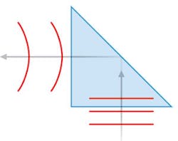
For example, if the measured transmitted wavefront was concave (see Fig. 1), an appropriately scaled amount of power could be polished into a single surface using MRF to compensate for the error. Which surface to use for this correction is determined based on a number of factors, including the size of the respective area to be polished and the amount of material required to impart the desired changes. Using this technique can potentially loosen the requirements on the conventional polishing steps on the three faces. As a result, correcting the transmitted wavefront with MRF can make the fabrication process more efficient while also yielding better-performing elements.
Continuous phase plates
Perhaps the best known, and certainly the most complex, examples of a "perfectly bad surface" are the continuous-phase-profile (CPP) plates that have led to significant advances in laser-fusion research. In use, each CPP—one of many in the system—contains a unique surface profile.
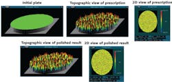
This profile is measured as the beam propagates along the beam path and through a plane-parallel window. Subsequent to the testing, the window is removed and modified by adding a complex topology that is essentially the opposite of the errors measured in the previous step, thus compensating for the undesirable phase anomalies (see Fig. 2). This allows researchers to manipulate the beam profile and ultimately the energy distribution at the target plane. These designs have included features with microns of amplitude variation over just a few millimeters of lateral position.While this compensation concept has been in use for quite a while, the traditional method for creating the phase profile—namely photolithography—is significantly constrained in terms of achievable accuracy and required part geometry. By using MRF and novel metrology techniques, the as-built phase plates, for beam diameters ranging from 1 to 18 in., agree globally to the prescription within a few nanometers root-mean-square (RMS). As a result, MRF has proven to be an enabling technology in this field with many documented and published results.1
Synthetic turbulence plates
Telescope systems incorporating adaptive-optics (AO) correction typically require a calibration step, which can be performed by viewing a known source in the nighttime sky. Obviously there is a desire to preserve the night viewing time by performing this calibration offline during the day. This can be accomplished with a transmissive synthetic turbulence plate.
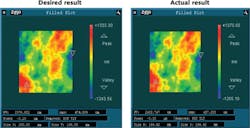
Similar to some of the CPP plate designs described previously, synthetic turbulence plates require a highly structured surface that is intended to replicate the as-measured nighttime turbulence. During the daytime, the plate is placed within the system and rotated at a constant rate to simulate the nighttime turbulence and to calibrate the wavefront sensors and control system. These plates can range in size from a couple hundred millimeters to near meter-class. For example, MRF was able to print a design that included several microns of desired error over a wide variety of lateral spatial frequencies (see Fig. 3).2Both the CPP and synthetic turbulence plates had a relatively simple-sounding specification (agreement with the prescription to within 10 nm RMS); however, this was simply to speed up progress on the shop floor before the more-detailed analysis was performed. For both types of plate, the final measured wavefront content was analyzed as a function of spatial frequency from 1 mm to a couple hundred millimeters (a good fraction of the aperture).
The data was further analyzed by modeling its system impact on encircled energy in a target chamber (in the case of CPP plates) and simulated atmospheric turbulence. Hence, while the top-level specification may sound relatively mundane, the later analysis precisely drove the manufacturing process decisions to selectively imprint the desired error patterns and maximize the system performance.
Optical assemblies
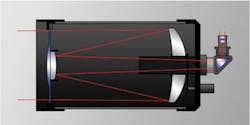
Another example of exploiting this unique capability is the concept of modifying a single surface in an optical assembly to compensate for errors residing elsewhere, in the hopes of yielding an enhanced system performance. The classic example of this is a Schmidt corrector in a telescope system, wherein a thin aspheric window is used to compensate for spherical error in the optical design (see Fig. 4).Similarly, MRF can be used not only to add the correction needed to improve the as-designed performance, but also to provide a way to compensate for errors resulting from the mounting of the other elements in the system, provided the system can be tested after it is assembled and the element to be compensated can be easily removed and reproducibly replaced mechanically.
Choosing the correct element to use as the compensator is once again not a trivial task, and often requires dialogue between the fabrication staff, the optical designer, and the opto-mechanical team. As long as the design lends itself to this type of correction and all involved are focused on producing a superior end product, it is likely that a suitable candidate surface can be found.
In a telescope system, for example, the secondary mirror is typically chosen as the compensator because it defines the pupil of the system, and the polishing cycle time scales with the area of the polished aperture. Figuring the secondary mirror in this fashion has been proven internally at QED Optics and by a number of MRF machine owners to efficiently create matched mirror pairs, resulting in enhanced telescope-system performance.
These days, it is safe to say that "precision optics" are not limited to those optics that are polished to be extremely flat or perfectly spherical. Many applications require custom-manufactured correctors or compensators; MRF is uniquely capable of creating such perfectly bad surfaces—and a few suppliers have become quite adept at producing these novel components in a production environment.
REFERENCES
1. J. Menapace et al., "MRF for imprinting continuous phase plate structures onto optical surfaces," Proc. SPIE, 5273 (2004).
2. J. Pazder et al., "Producing large synthetic turbulence plates using MRF polishing," Second International Conference on Adaptive Optics for Extremely Large Telescopes (2011).
About the Author
Mike DeMarco
Business Manager, QED Optics
Mike DeMarco, business manager for QED Optics (Rochester, NY), has spent over 25 years in the fields of precision optics manufacturing and optical system assembly and testing. He took over the management of QED Optics in 2011 after serving as QED Technologies’ sales manager since 2001. Prior to joining QED, he managed the Optical Assembly and Test Department for PerkinElmer and SVG Lithography Systems.
Christopher Hall
Senior Engineer, QED Optics
Christopher Hall is senior engineer at QED Optics (Rochester, NY).
