Advanced modeling helps design telecom systems
George N. Lawrence
With the explosion of interest in telecom devices, optical modeling codes must advance to meet the challenge. Fortunately the exponential growth of calculation power resulting from Moore's Lawwhich states that processing capacity doubles every 18 monthsmakes it possible to meet these demands. For instance, extensions to ray tracing have been devised to treat telecom devices such as microelectrical systems (MEMS) with free-space propagation methods such as paraxial Fresnel theory and Gaussian beamlet theories (see Laser Focus World, April 2001, p. 173).
Why are rays not sufficient? Rays assume the intensity distribution is both constant and uniform, but where intensity varies with propagation, the ray concept falls apart. So the usefulness of calculating ray trajectories in resonators or waveguides is highly questionable. Nevertheless, while rays are not very good at analysis of the detailed distributions in waveguides, ray-trace codes can be effective for designing aberration-free fiber-to-fiber or diode-to-fiber coupling optics where they fulfill their traditional role (which predates modern data processing) of minimizing optical path differences.
Numerical implementation of free-space diffraction propagation methods based on a decomposition into plane waves goes back more than 40 years to the work of Fox and Li at Bell Labs (when the available computing power was not much better than one would find in a modern home appliance).
Boosting precision
Modeling of high-divergence laser diodes, high-numerical-aperture fiberoptics, and many integrated optics applications, requires the more accurate vector diffraction theoryeven for free-space propagation and moreso for waveguide structures. The distinction is that when the diffraction half-angles exceed 10° or 15°, cosine effects become important and vector diffraction theory is necessary. A form of paraxial vector diffraction can be used to represent basic polarization properties of lenses, optical fibers, and waveguides with modest core-cladding index differences. Wide-angle vector diffraction demonstrates the details of strongly focused beams where linear polarization creates an elliptical image (paraxial Fresnel theory would predict the image to be circular) and gives us Ezthe component of the electrical field parallel to the direction of propagation.
Large differences of index between core and cladding in waveguides require wide-angle vector diffraction, but the calculation times are only about three times longer than scalar Fresnel diffraction and only about 50% longer than paraxial vector diffraction. Computer codes that can model wide-angle vector diffraction in free space include Diffract by MM Research (Tucson, AZ) and GLAD by Applied Optics Research (Woodland, WA). With this type of code we can model the output of a high-divergence laser diode or fiber and follow it through an optical system consisting of components such as lenses, mirrors, gratings, HOEs and apertures, and calculate the coupling into a waveguide or fiber.
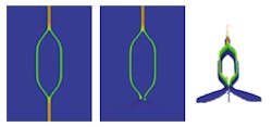
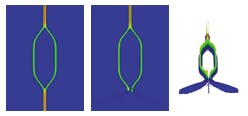
Light enters a photonic switch from above and splits into two branches. With identical legs the light adds coherently at the lower junction (left) so the switch is on. In the center image the index in part of the left leg has been raised just enough that it is now p out of phase relative to the right leg. So the beams add destructively and the switch is in the off position (center). Wide scattering of the light is visible in the lower part of the right image and is shown in an isometric view (right).
A common photonic switch can be modeled with the GLAD program in less than a second on a PC (see figure). It is convenient to tinker with the design parameters to get a feel for the physics involved or to build more-complex combinations of photonic widgets.
Waveguides, splitters, and couplers
Fourier methods, whether scalar or vector, rely on the fact that plane waves propagate unchanged through free space (they are eignefunctions of free space). So they present a natural method for air paths. Waveguides certainly are not the same as free spacethe high-index core tends to trap the lightbut we can model them by taking a small step of free-space diffraction (where the light diverges slightly) and adding the phase advance in the localized high-index regions (adding a slight convergence). This is the split-step method and it is the basis of the many forms of the beam propagation method (BPM). The BPM is wonderfully simple, but we can only take very short steps through a waveguide, often a fraction of a micron. We can observe the transient effects as light is injected into a waveguide or fiber, or find the steady-state solution by repeated propagation steps.
Slab waveguides are an important special case where light performs according to free-space theory in the plane of the slab and as a guided wave in the out-of-plane direction (through the thin, high-index film). The in-plane free-space propagation requires only two-dimensional (2-D) calculations. The thickness of the film sets the propagation constanta form of wavenumber and comparable to propagating with a somewhat higher index of refractionfor the in-plane free-space propagation. Ribs of various construction are added to the top of the waveguide to raise the effective index under the rib. The effect of the rib is to create a high index path in the waveguide below, like a gradient index effect. With the effective index method, one performs 2-D calculations for the in-plane direction and then calculates the height and width of the rib required to achieve that effective index. This allows the three-dimensional (3-D) calculation to be factored into a 2-D calculation for the in-plane effects and one-dimensional calculation for the out-of-plane effects to determine the index. For the most exact work, the full 3-D treatment may be required. Both Rsoft Inc. (Ossining, NY) and Optiwave Corp. (Ottawa, Ontario, Canada) have advanced software tools for waveguide analysis.
Devices that employ nearly copropagating beams such as directional couplers, y-splitters, y-combiners, optical switches, and so on, are relatively straightforward. For distributed feedback and other reflecting structures we must use a form of bidirectional BPM. Many applications such as sharp 90° turns, photonic bandgap structures (photonic crystals), microring filters, and resonators challenge or exceed the capability of BPM methods.
For advanced applications, the finite-difference time-domain (FDTD) method is the most exciting development. The FDTD is a direct attack on Maxwell's theory without the implicit assumption of directionality in BPM or presumption of well-behaved frequencies. Calculations are time consuming because of the need for subwavelength sampling over the full volume of interest and small time steps. Moore's Law of exponential growth of computer power will make FDTD increasingly practical. Both Rsoft Inc. and Optiwave Corp. have commercial FDTD products.
Which method should you use? For the best speed and good insight, use the simplest method that has the needed accuracy. Make sure that you understand all of the features and results that you see in your analysis. The software vendor should be able to provide documentation of the validation tests. Models validated only against experiment may be right for some cases and wrong for others. Validation should be against published theory. Look for software with documentation of the theoretical basis of the code and numerous examples for a range of applications.
GEORGE LAWRENCE is president of Applied Optics Research, 1087 Lewis River Rd. #217, Woodland, WA 98674; e-mail: [email protected].

