Switching is essential in telecommunications, but it can be confusing because it operates at two distinct levels. The telephone network includes many big, expensive boxes called switches, which contain dedicated special-purpose computers that direct the operation of small components called switches. To a network engineer, the big box is the switch, but to an optical engineer, a switch is a component inside the big box. Both the big box and the component can do optical switching, but with current technology the big box inevitably contains sophisticated electronic control systems. Only components can be "all optical," and this article focuses on various types of all-optical switching components that are available or in development for switching functions.
In practice, many optical switches actually are optoelectronic, with input optical signals converted to electronic form for switching, and the switched electronic signals then driving an optical transmitter. All-optical switches manipulate signals in the form of light, either by redirecting all signals in a fiber or by selecting signals at certain wavelengths in wavelength-division multiplexed (WDM) systems. Some switches can isolate individual wavelengths, but typically their input is individual optical channels separated by demultiplexing optics. That means they operate at the optical-channel level, without regard to what data stream the optical channel is carrying. Electronic or optoelectronic switches are still required to manipulate the data stream transmitted on each optical channel, such as breaking up a time-division multiplexed signal into its component pieces for distribution at the end of a long-distance transmission line.
One further distinction is between "transparent" and "opaque" optical switches. Most current all-optical switches are considered transparent because they transmit the original input light, without converting it into some other form, as if you could "look" right through it. One simple example is a moving-mirror switch, which reflects the input photons in different directions. Opaque optical switches convert the input photons into some other form, and thus do not transmit them. They include optoelectronic types and others that convert the signal to a different wavelength using optical or electronic techniques.
MEMS optical switches
Microelectromechanical systems (MEMS) have attracted wide attention for optical switching because of their versatility. Originally developed for display applications, MEMS are assemblies of tiny mechanical components fabricated by depositing layers on a substrate, then etching away selected material using standard photolithographic technology.
A variety of MEMS devices have been developed for optical switching that share common features. Typically movable components are suspended on flexible structures above a base layer. Either electrostatic or magnetic forces between the base and the elevated components move the structures. Electrostatic forces that create different charges are easier to control and are more widely used, but magnetic forces are stronger. However, magnetic forces—typically between an electromagnet on the surface and a magnet on the movable structurerequire shielding from external fields. Photolithography can fabricate many components on the surface, producing an array of identical switching components.
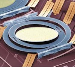
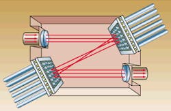
The designs can differ greatly in detail. One common approach is the two-axis tilting mirror (see Fig. 1). The central mirror pivots on one axis between a pair of posts attached to a surrounding ring. The ring, in turn, pivots on a perpendicular axis on a pair of posts connected to a surrounding framework, which is fixed in place above the surface. This design allows the mirror to scan in both the x and y directions and to reflect an input beam across a range of angles.Pairs of these arrays can be used as optical crossconnects, a type of switch that can connect any one of multiple inputs to any of multiple outputs. Light from an array of parallel input ports is focused onto one array of tilting mirrors, which redirect it to a second array; this in turn relays it to an array of output ports (see Fig. 2). The beams go through free space between the tilting mirror arrays; together they select which input beam is directed to each output port.
Many other optical MEMS switches are based on tilting mirrors, which offer some major attractions. Continuous tilting over a range of angles in two directions allows the mirror to reflect the input beam to many possible output ports. This feature supports a compact design with low component counts; the number of mirrors needed for an N x N switch scales as 2N, so a pair of 256-element arrays can interconnect 256 input ports with 256 outputs. On the other hand, the design requires extreme precision in pointing the mirrors; a slight misdirection can shift the output to a different port. Some engineers call tilting mirrors "analog" MEMS because they scan the reflected beams over a continuous range of angles.
A different approach, sometimes called "digital" MEMS, uses folding mirrors that move between two extreme positions, where they latch into place. Typically light beams travel parallel to the substrate, and the mirrors are either popped up into a position to light in a different direction, or "down" to allow light to pass straight through. Control circuits for these pop-up mirrors are much simpler, and latching into position assures accuracy. However, to make N x N connections, this design requires N2 mirrors, making component counts very high for systems with large numbers of ports. The largest arrays now considered practical are 32 x 32.
Strictly speaking, MEMS are mechanical switches, raising some concerns about the long-term durability of structures that flex repeatedly. However, MEMS devices are used in some commercial applications, including displays and sensors, and samples have been tested for billions of cycles without failure. Another important question is how well tilting-mirror MEMS can retain the required accuracy of around 10 µrad.
Waveguide bubble switches
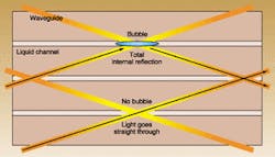
Another promising class of all-optical switches is based on bubbles moving back and forth in a liquid-filled channel that crosses intersecting silica planar waveguides. The planar waveguides have a refractive index higher than the substrate material, so normally they guide light along their length. The fluid channel contains liquid with the same refractive index as the waveguide and crosses the waveguide at the junctions.As long as the liquid is present, light travels straight through the waveguide junction. However, if a bubble is injected at the junction point, light in the waveguide undergoes total internal reflection and is directed down the intersecting guide (see Fig. 3). Bubbles can be produced by heating the fluid and can be moved back and forth through the liquid channel. The technology is similar to that used in ink-jet printers, indicating that such bubble switches should be mass-producible.
Like other optical switches with two possible output directions, the number of bubble-jet switching nodes increases with the square of the number of terminals. Thus, an array with 8 inputs and 8 outputs requires 64 waveguide junctions, where bubbles can move back and forth to switch signals. Other waveguide switches share the same scaling factor. Mechanical alignment is not critical in waveguides, but some skeptics wonder about lifetimes of the moving liquid and bubbles.
Solid-state waveguide switches
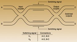
A common design for a solid-state waveguide switch is the Mach-Zehnder interferometer, in which a pair of parallel waveguides are joined at their output ends by a coupler with two outputs (see Fig. 4). The relative phase of the light in the two parallel guides determines from which output port the light emerges. Signals are switched or modulated by varying the refractive indices of the two parallel guides relative to each other, either by changing one guide while the other remains constant, or by changing the two simultaneously in opposite directions.In principle, any effect can be used to vary the refractive index, but in practice this is done either electro-optically or thermally. In an electro-optic waveguide switch, an applied voltage changes the refractive index of a nonlinear material such as lithium niobate; often a positive voltage is applied across one guide and a negative voltage across the other, to produce a larger relative phase shift. In thermo-optic switches, changes in temperature affect the refractive index of one guide, causing the desired phase shift and switching the light between the two outputs.
A key attraction of these waveguide switches is their solid-state nature, containing no moving elements whatsoever. Like bubble waveguide switches, the number of switching elements required increases with the square of the number of terminals, leading to large component counts. In addition, refractive-index changes are relatively small, so the waveguide switching elements must be relatively long—typically several millimeters to a centimeter for electro-optic switches.
Electroholographic and acousto-optic switches
Other principles also can be used to make all-solid-state optical switches. One is electroholography, in which application of an electric field activates a stored hologram written in a photorefractive material such as potassium lithium tantalate niobate. Without the electric field, no hologram is present, so light travels through the material normally. Applying the electric field increases the difference in refractive index between regions in which the hologram was written and other parts of the crystal, essentially turning on the hologram.
A holographic Bragg grating can serve as a wavelength-selective switch. Without the electric field, no hologram is present, and all wavelengths go straight through the crystal. With the field applied, the Bragg grating reflects the selected wavelength while transmitting others. Adding suitable optics creates a switch that can pick off a specified wavelength when desired.
Acousto-optic switching also relies on interactions between light waves and periodic variations in the refractive index of a material. An acoustic transducer couples acoustic waves into the crystal, which set up a pattern of refractive-index variations. Modulating or switching the acoustic signal changes the refractive-index patterns, switching the light in different directions.
Liquid-crystal switches
Liquid crystals can be used in switches as well as the more familiar use in displays. In both cases, the liquid crystal is a thin layer between a pair of parallel glass plates. Applying a voltage across the crystal layer switches it between one state that rotates the polarization of light passing through it, and a second state that does not affect polarization. With suitably arranged polarizing optics, the liquid crystal can function as a switch.Liquid-crystal displays work by transmitting light of one polarization but not of the other. Liquid-crystal switches separate the input light into two polarizations, which are reflected from liquid-crystal plates. Applying a suitable voltage changes the polarization of the reflected light, which the polarizing optics deflect differently than if its polarization is not rotated, switching it between output ports.
Switches in development
The importance of switching in optical networks continues to stimulate intense R&D of new optical-switching mechanisms. Many are variations on existing approaches, such as interferometric waveguide switches. Others are based on devices such as semiconductor optical amplifiers.Future switching applications will require pushing the technology further. One target is true optical routers, which like their electronic counterparts would read the headers on Internet packets and direct them to their destinations. That would require switches to operate on much faster time scales than the milliseconds or microseconds of current technology. The challenges are formidable, but given the success of recent years, it would be foolish to assume they are insurmountable.
About the Author
Jeff Hecht
Contributing Editor
Jeff Hecht is a regular contributing editor to Laser Focus World and has been covering the laser industry for 35 years. A prolific book author, Jeff's published works include “Understanding Fiber Optics,” “Understanding Lasers,” “The Laser Guidebook,” and “Beam Weapons: The Next Arms Race.” He also has written books on the histories of lasers and fiber optics, including “City of Light: The Story of Fiber Optics,” and “Beam: The Race to Make the Laser.” Find out more at jeffhecht.com.


