Tunable picosecond OPO enables trace gas detection
Wytze E. van der Veer
When performing spectroscopy with pulsed lasers, one faces an essential trade-off between pulse duration and bandwidth. For time-resolved measurements the pulse needs to be shorter than the observed phenomena. Also, when nonlinear effects are investigated, high peak intensities are required. Compression of the pulse energy into a short time interval will favor these processes. For frequency resolved measurements more detailed information can be obtained if the bandwidth of the laser is as narrow as possible. The pulse duration and the bandwidth of the laser are coupled through the Fourier limit, normally written as DeltavDeltat < 1, where Dn is the spectral bandwidth of the radition and Deltat is the duration of the pulse. Optimum temporal and spectroscopic information is obtained when DeltavDeltat = 1.
Our spectroscopy application consists of ultratrace detection of atmospherically relevant compounds with REMPI TOF MS (resonance enhanced multi photon ionization time-of-flight mass spectrometry). The target molecules include halogen oxides, such as HOCl, HOBr, ClOOCl, as well as radical species, including CH3OO and HO2. All these molecules dissociate rapidly when excited in the UV/VIS region. However, several relatively long-lived Rydberg states are expected closely below the ionization threshold. A two-photon excitation of these levels and consecutive ionization is expected to be a sensitive and selective probe for these molecules. So, to excite these molecules we need a short pulse to beat the dissociative process, an intense pulse to drive a two-photon transition, and a narrow bandwidth pulse to obtain as much spectroscopic information as possible about the investigated Rydberg states. Hence we need radiation with time-bandwidth specifications close to the Fourier limit. From earlier measurements we expect that the required duration of the pulses will be about 25 ps, the minimum achievable bandwidth will then be approximately 40 GHz (1.33 cm-1).
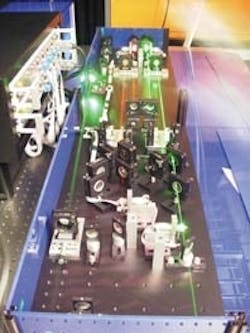
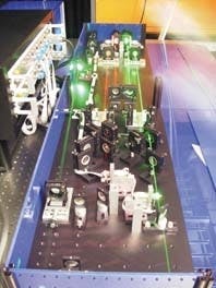
If it were possible to simply purchase a light source to meet these requirements, there would have been no reason for this article. Currently, however, such a system is not on the market. The best off-the-shelf product is an OPG (optical parametric oscillator) but it would not reach the Fourier limit. The bandwidth generated by such a device is on the order of 10 cm-1 with a pulse duration of 25 ps. Another option is to use a nanosecond OPO and to amplify the output pulse with a picosecond OPA. This requires a separate Nd:YAG laser and a narrow-band OPO with an intercavity grating, however. Also, one would need to take care of timing problems between these two lasers. Finally, the latter system simply would be too expensive for our application. Consequently, we set about constructing our own system, which is described below (see Fig. 1).
Pump laser and pulse train amplifierThe design of our tunable source is closely integrated with a commercial modelocked pico-second Nd:YAG laser (Ekspla PL2143B; Vilnius, Lithuania; see Fig. 2). The Nd:YAG crystal in head one is pumped with a flash lamp, enabling the cavity to build up an oscillation. The cavity is limited by the dye cell and a mirror on the left-hand side and a concave spherical mirror on the right-hand side. The dye causes modelocking, allowing formation of a single pulse with a duration of approximately 25 ps which travels up and down the cavity.FIGURE 2. Cavity of the Ekspla PL2143B modelocked Nd:YAG laser is formed by a dye cell and mirror on the left side and a concave spherical mirror on the right to provide modelocking. Note the additional output for the pulse train via P2.
This oscillation is stabilized by two Pockels cells PC1, and PC2. The PC1 is modulated with a RF signal closely adjusted to the round-trip time of the cavity. It effectively functions as a timed shutter forcing the oscillator to form a single pulse. The second Pockels cell, PC2 , introduces a loss into the cavity, which is electronically negatively coupled back to the intensity of the optical oscillation in the cavity. This allows the oscillator to build up a stable oscillation in approximately 250 round-trips while maintaining a low intensity with a well-defined duration and low intensity fluctuation.
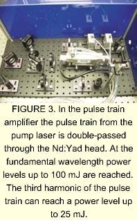
Once this pulse is well established, Pockels cell PC3 is activated, effectively making it a half-wave plate. As a result, the cavity is switched over to a second branch via polarizers P1 and P2, allowing the oscillator to gain intensity in about 10-round trips and completely deplete the population inversion in the Nd:YAG rod. In each passage of this pulse, a part is leaked via a quarter-wave plate and polarizer P2. Eventually the pulse in the oscillator gains sufficient energy and is dumped via Pockels cell PC4, and polarizers P3, and P4, . The pulse is further amplified in a double-pass Nd:Yag amplifier with a diameter of 10 mm. The output power at 1064 nm is 80 mJ. The power of the tripled wave at 355 nm is rated at 25 mJ, in a single pulse. The pulse train from the oscillator is further amplified in a double-pass amplifier (see Fig. 3).
The polarization of the incident beam is adjusted with a half-wave plate. The beam is made divergent with a negative lens to efficiently fill the 8-mm Nd:YAG rod. The beam passes twice through the rod and a quarter-wave plate and is picked up by the polarizer P. The beam is then rendered parallel with a positive lens. The second and third harmonics are generated in two deuterated potassium dihydrogen phosphate (DKDP) crystals. Energies of the pulse train at the fundamental wavelength of up to 100 mJ per shot have been observed. At 355 nm, an energy up to 40 mJ per shot can be obtained.
OPO and OPAIn this design the active element consists of two b-barium borate (BBO) crystals in a walk-off compensating arrangement (see Fig. 3). The crystals are cut for type I parametric generation over the range of 410 to 2000 nm. Each crystal is mounted directly on the axis of a stepper gear motor allowing the adjustment of the angle of each crystal individually. On one side each cavity is terminated with a flat mirror, CM1,2 which is highly reflective for the visible range. On the other side, the cavities are limited with a grazing incidence grating G1, 2 and a tuning mirror T1,2. The tuning mirror directs the diffracted first order back onto the grating, completing the cavity. The tuning mirror is mounted on a rotation stage with its axis of rotation positioned under the center of each grating, allowing the adjustment of the wavelength without changing the length of the oscillator. The oscillator is folded with two mirrors, allowing easy adjustment of the cavity length. A concave mirror is used to ensure optical stability of the cavity.The diameter of the pump pulse train is reduced with a telescope. The beam is then split with BS1 and directed into the BBO crystals via cavity mirrors CM1, 2 which are transparent for 355 nm. The remnant of the pump beam is coupled out of the cavity with a notch filter NF1, 2 and dumped.
The 0th order reflection of gratings is directed via two mirrors into the OPA crystal. The pump beam, the single pulse from the pump laser, is inserted and removed from the optical axis with notch filters NF3, 4, 5, 6. The timing between the pulse train and this single pulse is adjusted with the delay line D, optimizing the temporal overlap between the last pulse of the OPO and the pump pulse for the OPA. The diameter of the pump pulse is adjusted to fill the whole crystal.
BandwidthThe bandwidth of the output was measured using a thin etalon and found to be 1.36 cm-1 (full width half maximum), surprisingly close to the theoretical limit for a pulse with a duration of 25 ps. However, the commonly used definition of the Fourier limit DeltavDeltat = 1 assumes a pulse with a square temporal profile and spectral distribution within the first zero points of a sine function. When one makes the more realistic assumption that both the temporal profile and the spectral distributions are Gaussian functions, the Fourier limit is defined by DeltavDeltat = 4Ln(2)/pi = 0.88. A pulse with duration of 25 ps will then have a minimum bandwidth of 1.17 cm-1, still leaving room for improvement.The pulse train generated by the oscillator was recorded with a fast photodiode and a 1-GHz oscilloscope. The signals were recorded for pump energy 1.5 mJ (oscillator on threshold) up to 6 mJ (close to damage threshold). With increasing power the oscillator manages to start pulses off earlier in the pump train, resulting in more roundtrips. It is important both for the bandwidth and the stability of the generated radiation to make as many roundtrips as possible. At a pump energy of 6 mJ seven roundtrips have been observed. Also, the intensity of the pulses in the oscillator levels off while the intensity of the pulses in the pump train steadily increases. Earlier observations of a pulse train generated by an oscillator containing only one BBO crystal showed a maximum of three roundtrips at power levels dangerously close to the damage threshold, hence the need for using two crystals in a walk-off compensating configuration.
Output energyThe output power of the OPA was measured as a function of pump power (see Fig. 4). The diameter of the pump beam at the crystal is 3.5 mm. The power of the pulse train from the oscillator, pumped with a 6 mJ pulse train, is 170 µJ. Over the observed range the power gain increases linearly with pump power, no saturation effect is observed. The conversion efficiency for generating both signal and idler waves, determined from the slope of the linear fit to these data points, is 55%. The intensity of the output pulse was measured as a function of time and shows a clean single pulse.ACKNOWLEDGMENTS
Funding for the development and construction of this system has been obtained through the NSF-CRIF program.
Wytze E. van der Veer directs the Laser Spectroscopy Facility in the Department of Chemistry, University of California at Irvine, Irvine, CA 92697-2025; e-mail: [email protected].


