Rather than relying on separate mounts to keep everything aligned, space-filling solid optics are bonded together to form a single, mechanically stable component. This sort of unit can find application in telecommunications, where filtering and beamsplitting functions are often carried out by bulk optics. Researchers at the NEC Research Institute (Princeton, NJ) have developed a solid-optics component, termed an X-cube, that performs various lossless beamsplitting and filtering functions among four input beams, as well as add/drop multiplexing and other operations.1
The X-cube is simply a beamsplitting cube that has two, crossed, partially reflecting inner surfaces instead of one. Collimated light beams are sent through the cube and get split or combined. The optical coatings on the surfaces can have either spectrally independent or dependent reflective properties; the arms of the X can be coated either the same or differently for a total of four distinct coatings. Eight ports exist—an input and output port on each face of the cube.
If all four reflection coefficients are chosen to be 0.5, the X-cube can be used as a lossless 4 x 4 beamsplitter. In this case, each output receives a quarter of the optical power from all four inputs. The cube can also be configured as a star coupler for four-channel coarse wavelength-division multiplexing (CWDM). Here, each of the four reflective planes (arms of the X) is coated differently such that it transmits two of the four wavelengths while reflecting the other two.
In yet another configuration, the X-cube becomes a two-channel CWDM add/drop multiplexer that downloads data transmitted by two wavelength carriers out of many possible CWDM channels and simultaneously uploads new data to the two wavelength carriers. In this case, only six ports are used—two for the main input and output channels carrying all the wavelengths, two for the dropped channels, and two for the added channels. The researchers also envision coating the four planes with polarizing coatings, making polarization-coded beamsplitting and filtering possible; or adding active switching capabilities to the planes.
Precise construction of the X-cube is necessary. For a prototype, the researchers fabricated four right-angle rooftop prisms of 35-mm base length with 6-s angular precision for the 90° angle and 15-s precision for the two other angles. All prism faces were made flat to within one optical fringe. The prototype X-cube has identical coatings on its four planes: a multilayer dielectric with a 50/50 splitting ratio at a wavelength of 1300 nm. Cementing the four prisms together required no active alignment. Each of two prism pairs was placed on a flat surface and brought up against a perpendicular surface, then glued. The two bonded pairs were then glued together using a flat reference plane.
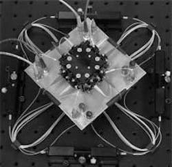
The assembled X-cube was mounted into a 4 x 4 optical star-coupler module containing eight multimode fiber collimators (see figure). To eliminate polarization dependency induced by the dielectric coatings, a polarization controller was inserted between each input fiber and the cube (alternatively, birefringent optics can be used). Average total insertion loss for each input-output pair was 2.1 dB. Uniformity (or actual splitting ratio divided by ideal splitting ratio) was 1.036 after final alignment.
The final size of the prototype star coupler was 70 x 70 x 70 mm. "From an optical point of view, the smaller the better," said Jan Popolek, one of the researchers. "Scaling down is technically more demanding, but would ease the requirements on the collimators and increase the requirements on lateral alignment precision."
REFERENCE
- J. Popolek and Y. Li, Opt. Eng. 40 (7), 1212 (July 2001).
About the Author
John Wallace
Senior Technical Editor (1998-2022)
John Wallace was with Laser Focus World for nearly 25 years, retiring in late June 2022. He obtained a bachelor's degree in mechanical engineering and physics at Rutgers University and a master's in optical engineering at the University of Rochester. Before becoming an editor, John worked as an engineer at RCA, Exxon, Eastman Kodak, and GCA Corporation.
