Know the trade-offs when specifying mirrors
DAVID COLLIER , WAYNE PANTLEY, and DAVID KEMP
Mirrors are ubiquitous optical components that are used in virtually all types of laser systems. Designers of such systems, however, do not always fully comprehend the meaning of all the various parameters used to specify a high reflector. This lack of understanding can result in the use of components that fail to meet the minimum performance requirements for the application, or in overspecified mirror performance that adds unnecessary cost. It is particularly important to understand the implications of mirror specifications for high-performance laser systems in which performance and cost can be critical. These considerations are even more important for ultraviolet (UV) laser applications.
The quarter-wave stack
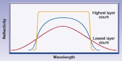
Most high reflectors for demanding laser systems use all-dielectric thin-film optical coatings. The simplest type of high-reflection coating is the so-called "quarter-wave stack." This coating consists of alternating layers of two different materials—one with a high index of refraction and the other with a lower index. The optical thickness of each layer is one quarter of the wavelength at which peak reflectivity is desired. The reflectivity of this type of coating increases with the number of layers (see Fig. 1). Raising the ratio of the refractive index of the two coating materials also increases the maximum reflectivity as well as the spectral bandwidth.
For a mirror used at a single wavelength and angle of incidence, the basic quarter-wave stack design is often adequate. Indeed, a reflectivity of greater than 99.5% is not difficult to achieve under these conditions for most visible wavelengths. However, the layers can only be exactly one quarter-wave thick at a specific wavelength and angle of incidence. Broadening the bandwidth of a quarter-wave stack with respect to wavelength or incidence angle (or both) is usually achieved in two ways, which can be used either individually or in combination. The first is to simply deposit two or more quarter-wave stacks centered at different wavelengths on top of each other. The second approach is to slightly vary the layer thicknesses within a single quarter-wave stack.
Performance trade-offs
A mirror with high peak reflectivity and broad bandwidth can be produced using a quarter-wave stack having many layers composed of two materials with a large difference in refractive index. A coating of this type, though offering good optical performance, may exhibit other characteristics that are less desirable. For example, thicker coatings (high layer counts) typically exhibit higher levels of internal mechanical stress than thinner coatings. In general, this stress reduces the overall mechanical durability of the film and can make it more prone to crazing.
Another problem is related to the materials themselves. The high refractive index required for broad spectral characteristics is usually obtained by using titanium dioxide. Unfortunately, titanium-based materials do not possess good laser-damage resistance characteristics. Better damage resistance can be obtained by using lower-index materials such as hafnium dioxide. Thus, there is often a tradeoff between the spectral performance of a coating and its laser-damage resistance.
These effects are particularly pronounced in the deep UV (especially below about 220 nm). Virtually no oxide coating materials can be used in the deep UV because they have significant absorption at these wavelengths. The fluoride materials that are useful in this region all have a relatively low refractive index, and therefore require a large number of layers to achieve high reflectivity. In addition, these fluoride materials are particularly brittle and prone to crazing. This tendency magnifies the tradeoff between optical performance and damage resistance and makes producing durable, high-performance coatings for the deep UV extremely difficult, necessitating tight process control.
Because of these trade-offs, it is essential not to overspecify mirror spectral performance. Demanding performance that is not really necessary, or placing too many constraints on certain parameters, can result in a component with some undesirable characteristics or excessive cost.
Flatness
Flatness (or, in the case of curved parts, surface figure) would seem to be one of the most straightforward mirror specifications. Flatness can be measured accurately using interferometry. Issues with flatness become significant for tightly toleranced parts at twentieth-wave (l/20) and beyond. Problems arise because a number of factors can perturb the part or frustrate the measurement process at this high degree of flatness. In fact, a nominally l/20 mirror can be easily distorted out of specification by its mount or by thermal effects. Consequently, a flatness measurement of l/20 made by the manufacturer may not be reproducible if the user performs the test with other mounting hardware or at a different temperature.
It is also important to realize that many manufacturers only specify the flatness of a mirror substrate prior to coating (precoating), rather than after (postcoating). This is an important distinction because the coating itself can be under stress, causing distortion of the mirror. Thus, a coated mirror can be distorted while still technically meeting published flatness. This problem is of particular concern with high-reflection coatings because they typically contain many layers and thus a higher total amount of stress.
Various methods of compensating for coating stress have been investigated. For example, if the coating stress is well-characterized, the substrate can be made slightly curved so that the coating stress serves to pull the part back to its desired flatness. Alternatively, a second coating can be deposited on the rear surface of a component for the sole purpose of equalizing the mechanical stress on the part. These techniques and the entire issue of postcoating flatness, however, remain problematic for two reasons. The first is that coating stress is rarely well-understood or consistent enough to enable the types of compensation just described to be quantitatively applied, at least on a volume basis. The second is that coating stress is both time-varying and dependent upon environmental conditions such as temperature and humidity. For example, a part measured at l/20 by the vendor just after production may have changed shape by the time it is evaluated by the end user.
Another major factor in achieving high flatness is substrate choice. It is not realistic to specify l/20 flatness with substrates having a relatively high thermal expansion coefficient (for example, BK7 glass). A low-expansion material such as fused silica is a much better choice.
Those who require high surface flatness should keep two things in mind. First, understand how the vendor specifies flatness (pre- or postcoating) and how measurements are performed. Second, control part temperature and ambient humidity and carefully examine how parts are mounted so as to maintain flatness over time.
Laser-damage threshold
Laser damage is a murky subject, and compliance with damage specifications is often a source of controversy between manufacturers and end users. The problem is that a mirror can meet its stated damage threshold specification, yet still be damaged in operation. This is because laser damage is often caused by external factors, which can be transient and difficult to identify.
One of the most common causes of damage when working with high-energy pulsed lasers operating in the visible and near infrared is the presence of "hot spots" in the beam structure (see Fig. 2). A hot spot is a region of the beam that possesses a considerably higher fluence than the nominal value. Indeed, it is not uncommon for the peak fluence in a hot spot—which may last for only a pulse or two—to exceed the specified output of the laser by a few orders of magnitude. This high fluence causes intense local heating and actually ablates part of the coating. Since the laser may quickly return to normal operation after producing a hot spot, this leads the user to believe that the mirror has failed at the nominal fluence level.
What does this mean in terms of specifying component damage threshold? First, it is important to characterize the laser system being used. Excellent beam-characterization hardware is available on the market; tests with this equipment should be performed to determine what type of peak fluence levels are really likely to occur, since these may be substantially higher than stated in the laser manufacturer's literature. It is also advisable to regularly examine and maintain laser alignment, since misalignment is a prime contributor to the conditions that generate hot spots. In practice, however, it may be more economical to accept a certain rate of damage, rather than specify a damage threshold sufficient to survive the peak fluence of the worst hot spots.
Another common cause of damage is contamination of the optical surfaces. This can come from a variety of sources, such as dust, fingerprints, water vapor, airborne oil (from pumps and so on), and outgassing from adhesives. Contaminants cause damage because they absorb laser energy and heat the coating. Again, this type of damage is often mistaken for failure of the coating; it is especially difficult to distinguish between coating failure and failure due to contamination when dealing with molecular contaminants that cover the entire surface of the mirror. The good news is that much of this type of damage can be prevented. For example, water vapor and dust can be largely eliminated by physically enclosing the beam path and filling the enclosure with a positive pressure of filtered dry nitrogen. It is also important to scrupulously adhere to proper optics cleaning procedures.
Physical characteristics
The nature of the various shaping and polishing processes used to produce optical components tends to make it difficult to simultaneously hold tight tolerances on certain sets of parameters. For example, achieving a precise wedge angle may require several rounds of polishing, with each round removing material from the thickness of the part. This process makes it difficult—and therefore more costly—to fabricate mirrors with a tight tolerance on both wedge angle and center thickness. The same logic applies to the parameters of center thickness and flatness. Again, a lengthy polishing cycle may be necessary to produce high flatness, and this makes it hard to predict how much total material will be removed from the thickness of the substrate in advance. This is also true of surface quality (called scratch and dig) and flatness. The longer an optic is polished, the more chance there is that it will be scratched. Therefore, a tight specification on both surface quality and flatness drives up cost.
No single mirror design is optimum with respect to performance, durability, damage resistance, and cost. Therefore, it is critical for the end user to set priorities on mirror parameters and to then clearly communicate these priorities to the manufacturer. Moreover, a full review of mirror specifications with the vendor prior to fabrication is a vital step, especially for original-equipment manufacturers, because this gives the manufacturer a chance to identify specifications that may drive up cost unnecessarily.
David Collier is president, Wayne Pantley is sales manager, and David Kemp is regional sales manager of Alpine Research Optics, 3180 Sterling Circle, Boulder, CO 80301; e-mail: [email protected].