On the page or on the screen, we are accustomed to looking at two-dimensional images of three-dimensional objects. For many applications, two-dimensional (2‑D) displays are sufficient. But users need or particularly want depth for some applications such as viewing tomographic medical images, modeling complex molecules, designing complex-shaped products, gaming, or military planning. (For groundbreaking work on capturing 3-D images, see “Imaging in 3‑D with holographic optical elements”). Stereoscopic and volumetric 3-D displays are being developed and marketed for these applications.
Seeing double
Stereo imaging, in which the left and right eyes see slightly different images, is a mature concept that is very popular, and the specifics of presenting stereo images continue to advance. These methods require that one eye not see the view presented to the other eye. In the venerable Viewmaster stereo slide viewer, two separate images are presented and a physical barrier blocks the unwanted view. (This method is still used for some systems that use one microdisplay for each eye). Having the viewer wear glasses with some sort of filter to remove the unwanted view has also been popular: cardboard glasses with color filters have sufficed for 3-D movies since the 1950s. In the past decade, new designs have used either passive polarized glasses or glasses containing liquid-crystal shutters synchronized to the frame rate. With wireless control, those glasses have become more user-friendly.
But in general, users don’t want to wear glasses. Several methods of implementing autostereoscopic systems are on the market—all use a barrier or filter close to the display to block the unwanted view. The barrier can be an array of microlenses, a film barrier, liquid-crystal shutter, or other device. Recent developments reported in May at the annual meeting of the Society for Information Display (Boston, MA) involve making robust switching elements for displays that can be used as either conventional (2-D) or 3-D displays.
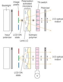
Graham Woodgate and Jonathan Harrold from Ocuity (Upper Heyford, England) describe using a 1‑mm-thick freestanding liquid-crystal microlens array that changes the mode of the display.1 “Essentially we produce a switchable lens component,” explains Paul May of Ocuity. For one polarization of light, the passive, birefringent lens does not act like a lens at all and the viewer sees a 2-D image. For the orthogonal polarization, however, the lens does act as a lens, refracting the pixels underneath, and directing light from each pixel to one eye or the other. “Typically, two pixel columns are imaged by each lenticular lens, and alternate columns are imaged on the left and right viewing windows,” he adds. The microlens array allows 3-D data to be displayed on a standard display (see Fig. 3).Physical Optics (Torrance, CA) offers an alternative to the flat-panel solution described above. The right and left views are both projected onto a screen with a diffraction patterned surface, which then directs the right and left eye views to where the viewer’s eyes are—or, with a different holographic screen to all of several viewing zones (see Fig. 1). The eyestrain from looking at this display is less than from a CRT monitor, according to Rick Shie of Physical Optics.
Problems with stereo
Eyestrain is a major drawback to using stereoscopic images. In an invited talk at SID, Brian T. Schowengerdt and Eric J. Seibel of the University of Washington (Seattle) explained why stereo systems are so fatiguing to view, and demonstrated a system designed to be more comfortable to watch.2 People determine depth using two effects: vergence (crossing the eyes more to look at near objects, looking along parallel paths at objects far away) and accommodation (eye muscles squeeze the lens inside the eye to focus near or far), and these two processes are linked. A typical stereo display varies the vergence but not the accommodation.
The researchers used a deformable mirror to match both depth cues. A laser system scans multifocal video directly onto the retina of each eye. As the scanning beam projects different virtual images, its focus is varied electronically using a deformable membrane mirror. By placing the virtual image of a rendered object at a focal distance that matches its stereoscopic viewing distance, the cues to accommodation and vergence match.
“It completely duplicates the effect the eye likes to see with distance by changing the focal length of the image as it is presented to the eye,” says session chair David Eccles, an engineering management consultant based in Valley Center, CA. “It is ground breaking work.”
Approaching volume
Several other designs provide accommodation cues, although not as sophisticated as the University of Washington system. Neurok Optics (San Diego, CA) has a display monitor with two panels—by showing a different image on each, the eye perceives a difference in depth. LightSpace Technologies’ (Norwalk, CT) DepthCube stacks 20 liquid-crystal screens to approximate a solid image. At any given time, 19 of the screens are transparent, and one screen is translucent, acting as a screen for a rear-projection display. The screens are switched quickly to take advantage of persistence of vision.
Flat-panel displays, even stacked, may be sufficient for an application, but they do not truly display volume. Volumetric displays present actual three-dimensional images, but typically at a higher cost. Unlike the stereo systems that use relatively standard displays, these require specialized equipment. By projecting an image onto a rapidly spinning screen, 3‑D images can be formed. Even when the screen has moved to another location, a viewer’s persistence of vision retains the image. A variant on this idea, using rotating light sources rather than light projected onto the screen, was reported at SID by Yasutada Sakamoto and others.3 Part of the challenge of making these systems is mechanical—the moving screen must be well-balanced and free of vibrations that could blur the image—as well as integrating the display with standard 3‑D software packages. And, as ever, cost is an issue.
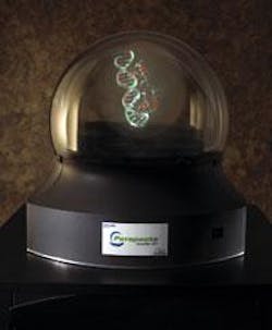
Resolution is also an issue, because volumetric displays need far more picture elements (voxels) to match the apparent resolution of planar displays. “Customers expect approximately the resolution of a desktop monitor,” says Gregg Favalora, CTO and cofounder of Actuality Systems (Bedford, MA). “But with 200 depth planes, we need 200 times the resolution.” Actuality Systems’ volumetric display, Perspecta, has roughly 100 million voxels: nearly 200 planes and each plane has 768 × 768 pixels displayed over a volume about 10-in. in diameter.
All the planes intersect in a line, spinning around a vertical axis. Because the images need to be changed quickly, the system refreshes at a rate of 30 volumes per second, Favalora says. The custom electronics and digital light processor from Texas Instruments generate 6000 2-D images each second. All this comes with a price tag of roughly $70,000, several times the cost of most stereoscopic displays—so the display is in use only for high-value applications, including medicine and oil drilling. “The benefits of spatial displays are in rapidly understanding time-varying data and in finding information that’s hidden inside something complex,” says Favalora.
For data that doesn’t vary much over time, digital holograms may fit the bill. At least one company, Zebra Imaging (Austin, TX), creates holograms from computer files to display data. The holograms cannot display video images, but the company does have techniques that allow some movement. The holograms can show short animations by showing different images from different angles—much like the classic girl-blowing-a-kiss hologram (see Laser Focus World, June 2005, p. 69). The company also can project 2-D video onto the hologram, which can provide more information than just standard video or just the 3-D static hologram. The company is marketing the technology to automotive design and military users.
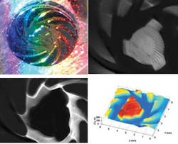
Another option for displaying 3-D data—albeit completely static—is to create a physical model. Rapid prototypers, such as the one produced by Z Corp. (Burlington, MA), can quickly create solid models from digital data (see Fig. 2). According to the company, a mobile phone design can be turned from a screen image into a prototype in under an hour for less than $10.
Development of the technology will likely continue. “I have been involved in 3-D display development with SID for more than 15 years, and I see that we still have a long way to go,” Eccles says. “Developing displays that are comfortable to the eyes and have high resolution are the big challenges that still remain. I believe we are still in the infancy of the field.”
REFERENCES
1. G. J. Woodgate, J. Harrold, Paper P-183L, SID 2005.
2. B. T. Schowengerdt and E. J. Seibel, Invited Paper 7.1, SID 2005.
3. Y. Sakamoto et al., Paper 7.2, SID 2005.
Imaging in 3-D with holographic optical elements
Classical optics is a well-developed method for capturing two-dimensional representations of three-dimensional objects—but it doesn’t capture depth information well. Several methods can be used to capture information about objects in all three-dimensions, including holography, interferometry, confocal microscopy, optical coherence tomography, and computer aided tomography.
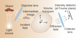
A 3-D optical imaging method that has as much to do with CAT scans as with traditional imaging optics is being developed by George Barbastathis along with coworkers at MIT (Cambridge, MA), CalTech (Pasadena), and Ondax Corp. (a volume-hologram manufacturer; Monrovia, CA).1 Volume-holographic imaging works like a pinhole confocal microscope, in that light from a plane of a particular depth can be selected while light from other planes is rejected. Instead of using a pinhole, however, the systems use an iron-doped lithium niobate crystal that contains a volume hologram (that is, a 3-D diffraction pattern).
The hologram is not a detector, but an optical element. Some light from the object will be strongly diffracted (see Fig. 1). The intensity of the diffracted pattern provides all the information necessary to determine the 3-D location (and possibly color) from a slice of the object. Data can be gathered from multiple depths by scanning the crystal or recording multiple holograms within the crystal. The data can then be reconstructed into a 3-D model of the object.
Volume holograms were popular elements investigated for use in optical data storage and optical interconnects. Some of the complex field transformations and feature extraction methods developed for these applications can be applied to imaging applications. Volume holograms provide a larger number of degrees of freedom in defining the optical response.
The volume holograms have some materials limitations. The diffraction efficiency is low, and if multiple holograms are recorded in a single volume the efficiency of each hologram drops further. In theory, diffraction efficiencies could be near 100%.
The promise of volume-holographic imaging is that the hologram can be manipulated to diffract different features of interest and the post-processing methods (already developed for tomographic imaging) can also optimize the imaging.
The holograms process color in unusual ways. The group took advantage of this to improve depth resolution without scanning.2 An object is illuminated with a rainbow of quasi-monochromatic colors. The reflected light, arriving at the volume hologram is diffracted at different angles, depending on the color. The colors act like depth-selective confocal slits (see Fig. 2). “The color slits work in parallel to achieve a wide field of view,” say the researchers. They demonstrated a better than 250-µm depth resolution over a roughly 15° field of view at a 50‑mm working distance.
Volume-holographic imaging systems have been demonstrated in a confocal microscope with the volume hologram replacing the pinhole, a real-time nonscanning four-dimensional hyperspectral microscope, a long-range surface profilometer, and a volume-holographic spectrometer.
REFERENCES
1. A. Sinha, et al., Opt. Eng. 43, 1959 (2004).
2. W. Sun and G. Barbastathis, Optics Lett. 30 (9), 976 (May 1, 2005).


