OPTICAL SWITCHES: Nonlinear microring resonators forge all-optical switch
ALASTAIR McAULAY
The microring resonator is a versatile component that provides a building block for fast, integrated, all-optical switches that lower cost and improve performance by reducing the number of optical-electronic conversions during a communication.1, 2 Nonlinear Kerr material in the core of the microring provides optical control for switching an optical data path. This optical control provides faster switching than electronic control and preserves optical homogeneity. Companies such as Intel (Santa Clara, CA) are investigating silicon modulators and silicon lasers with a long-term goal of integrating both optics and electronics on a single chip.3, 4 From the basic microring filter, different types of all-optical nonlinear resonator switches can be described, including on/off, frequency, and latching types.5, 6
Microring add/drop filter operation
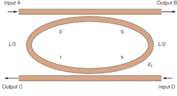
An open microring resonator add/drop filter consists of two straight waveguides between which is a circular or racetrack-shaped waveguide, each with widths that support single-mode propagation (see Fig. 1). Light of wavelength λn enters the left input arm of the upper straight waveguide and is coupled into the microring. If light arriving back at its input point after traveling once around the microring is in phase with new light entering the microring from the original input location, the energy will build up over time until the intensity of the light in the microring is many times that at the input, analogous to building up energy in a child’s swing. The phase match for resonance occurs only if the distance around the microring, L, is a whole number m of wavelengths in the material of equivalent refractive index ne, or L = m(λn/ne).

With time, the energy stored in the microring increases up to a steady state for which energy lost in one trip around the microring matches energy provided at the input during the same time.
Coupling occurs when the straight waveguide and the microring are sufficiently close that their evanescent fields overlap-the amount of overlap determining the coupling strength. Because the driving field in one waveguide of the coupler induces the driven field in the other waveguide through polarization, the phase for the driven field lags behind that of the driving field by π/2. At resonance, light coupling out of the microring into the upper right arm of the straight waveguide is out of phase with the light traveling directly through the straight waveguide because the coupled light experiences two π/2 phase changes, one from the light coupling into the microring from the straight waveguide and the other when the light couples out of the microring into the straight waveguide. Consequently, destructive interference at the output of the upper straight waveguide creates a bandstop filter centered around the resonant wavelength.
Light also can be coupled out of the ring from the left arm of another straight waveguide below it, to provide a bandpass filter or act as a frequency drop multiplexer at the resonant wavelength. If light of resonant wavelength is input to the ring from the right side of the lower straight waveguide (a control signal), it will appear at the top output and the microring will act as a frequency-add multiplexer.
Optimizing the filter
Critical optimization parameters are the size of the microring and the coupling coefficient, which can be adjusted by varying the spacing between the straight waveguide and the microring. Small-radius microrings allow large-scale integration but have greater bending loss because the evanescent tail of the field in the cladding cannot exceed the cladding phase velocity, so is unable to keep up with the wavefront around the bend. The evanescent tail is shorter for high refractive-index contrast between core and cladding, therefore the bending loss is reduced but the waveguides must be closer, requiring more-precise lithography.
The coupling coefficient must be adjusted to match the magnitude of the out-of-phase fields at the bandstop output to achieve a better than -20-dB drop in output at resonance for destructive interference. A small coupling coefficient with a low-loss microring allows many iterations to the field in the microring before steady state is reached and consequently, higher energy storage. This raises the quality factor, Q, defined at resonance as the angular frequency times the energy stored in the microring divided by the power lost for one trip around the microring. A filter with larger Q stores more energy and has a narrower frequency response, but is slower because of its time constant (Q divided by angular frequency). In telecommunications applications, Q is limited to a figure in the thousands due to the available recovery time of 50 ps for switching a typical 10‑Gbit/s optical data stream.
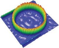
Simulation of the optical field at resonance for a microring with a high refractive-index contrast between the core and cladding of the waveguide structure shows a buildup of power in the microring at resonance (see Fig. 2). Light enters at the upper left straight waveguide, builds up power in the microring at resonance, cancels at the top right bandstop output of the upper straight waveguide, and exits at the lower straight left waveguide bandpass output. The bandpass intensity is smaller than the input power because losses are high for such a small radius.
Nonlinear microring on/off switch
An all-optical on/off switch can be constructed from a nonlinear switching microring structure tuned to the input signal wavelength (ring1) and a bandstop filter structure tuned to a control signal wavelength (ring2; see Fig. 3).
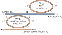
When signal light (wavelength λ1) enters the first microring structure, the field builds up to its resonance value and the switch is off because of previously discussed phase cancellation at the output.
But when a control signal (wavelength λ2) enters the input, the power in ring1, Pf, rises further, causing the effective refractive index ne to increase according to ne = n0 + n2Pf /Aeff.
Here, n0 is the baseline refractive index, n2 is a nonlinear coefficient, and Aeff is the effective area of the microring cross section. From the relationship L = m(λn/ne) defined previously, resonant wavelength increases with ne, moving ring1 away from resonance and allowing the input signal to pass to the output of the microring to turn the switch on. To remove the control signal from the input signal, the second microring, tuned to the control signal wavelength, resonates (at wavelength λ2) and the control signal light is removed.
Nonlinear microring frequency switch
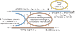
Different frequencies represent different communication channels in wavelength-division multiplexing (WDM), so instead of switching paths, frequencies can be switched (see Fig. 4). In simple terms, the intensity of a control signal, input to a microring that is adjacent to the input microring of the on/off switch previously described, sets the resonant frequency of that microring. Wavelengths input to the structure can be added or dropped as a function of the control-signal intensity.
Reconfigurable optical add/drop multiplexers (ROADMs) designed using this technology will significantly reduce telecommunication costs, compared to current technologies that require expensive connections for numerous, discrete optical components. Frequency switchers in WDM are analogous to time-slot interchangers that are prevalent in time-division multiplexing (TDM).
Nonlinear microring latching switches
In Internet packet switching, a header is decoded to latch an electronic routing switch to allow a following data-packet payload to pass. Therefore, the all-optical on/off switch needs to remain set after the control signal is returned to an equilibrium position. By selecting certain operating parameters, a nonlinear microring exhibits hysteresis for bistability that can latch an on/off switch into one of two stable positions.
When an equilibrium intensity is provided at the control signal input to place the microring close to resonance, the output may be in only one of the two stable states-high or low-depending on the past history of the control input. The switch is set to a high level with an input pulse that pushes equilibrium power to above the maximum input power that exhibits hysteresis. To reset the switch to a low level, a negative input pulse is used that lowers the equilibrium power to below the minimum input power that exhibits hysteresis. Hysteresis is useful not only for converting an on/off switch to a latching one, but can also be used to provide all-optical memory, shift registers, and sequential logic.
Transferring microring resonator switches from research to application will require continuing improvement in nonlinear optical materials to reduce required power input. Fabricating optical integrated microring switches in silicon and the development of silicon modulators (or lasers) could eventually lead to mechanisms for merging optical and electronic integrated circuits onto a single chip.❏
ACKNOWLEDGMENTS
The author wishes to thank the Center for Optical Technologies at Lehigh University and its director, Tom Koch, for their support, and Optiwave (Ottawa, ON, Canada) for simulation software.
REFERENCES
1. V. Van et al., IEEE J. Selected Topics In Quant. Electronics8(3) 705 (May-June 2002).
2. A. McAulay, SPIE proc. 5814, Security and Aerospace Applications, Orlando, FL, 16 (April 2005).
3. A. Liu, et al., Nature427(6975) 615 (February 2004).
4. H. Rong et al., Nature 433(7023) 292 (January 2005).
5. B. Little et al., IEEE Photon. Tech. Lett.16(10) 2263 (October 2004).
6. T. Ibrahim et al., IEEE Photon. Tech. Lett. 15(10) 1422 (October 2003).
ALASTAIR McAULAY is a professor in the Electrical and Computer Engineering department of Lehigh University, 19 Memorial Drive West, Bethlehem, PA 18105; email: [email protected].