MICROSCOPY: New techniques expand multiphoton imaging
Multiphoton imaging can reach beyond the realm of fluorescently labeled cells to include integrated circuits and dielectric interfaces.
Bruce Craig
In recent years, ultrafast laser pulses have had an increasing impact on the confocal fluorescence microscopy of cells and subcellular structures in the field of microbiology. Through multiphoton absorption, these pulses allow acquisition of three-dimensional (3-D) images of living cells with micron-level spatial resolution.
Researchers have now extended multiphoton imaging with several longer-wavelength techniquesbased on the latest generation of ultrafast optical parametric oscillators (OPOs) and optical parametric amplifiers (OPAs)that do not require the presence of a stain or fluorophore in the specimen. These techniques offer the potential for probing such disparate materials as optical fibers and integrated circuits (ICs).
Multiphoton microscopes
A confocal microscope uses a high-numerical-aperture (NA) objective to focus a laser beam to a small spot within a sample that has been stained with a fluorescent marker (fluorophore). The resulting fluorescence is focused onto a tiny confocal aperture before reaching a high-gain photodetector. This pinhole provides z-axis (depth) discrimination by blocking all fluorescence except that excited at the focus of the laser beam. By scanning the focused spot (or moving the sample), a full 3-D image can be built up point by point.
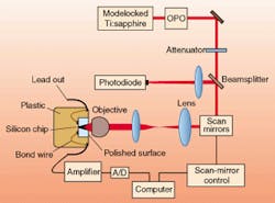
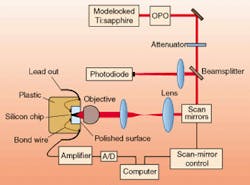
FIGURE 1. Experimental setup used for two-photon OBIC is based on a modelocked Ti:sapphire laser pumping an optical parametric oscillator.
The use of ultrafast lasers to drive two-photon absorption in confocal microscopy was described in 1990, when it was demonstrated that high peak intensities obtained at the focus of an ultrafast laser beam are sufficient to create two-photon (and even three-photon) absorption by the fluorophores.1 The effect diminishes rapidly away from the beam waist as the intensity falls off, which provides inherent z-axis discrimination so that the confocal aperture and associated throughput losses can be eliminated. In addition, multiphoton imaging with near-infrared (IR) laser pulses greatly reduces tissue damage caused by laser-beam absorption, as well as minimizing problems due to scatter of short-wavelength visible or near-ultraviolet (UV) excitation sources. As a result, the technique has rapidly gained popularity, because it allows living cells to be probed in real time.
Variations on this basic approach are now being developed, including the sweeping of multiple focused spots for higher-speed image acquisition and the use of two interfering laser beams to produce enhanced spatial resolution.2,3 Two entirely new multiphoton imaging methods are potentially even more important, however. Both two-photon optical-beam-induced current (OBIC) in semiconductors and third-harmonic-generation (THG) imaging of interfaces, films, and membranes do not rely on fluorescence detection at all.
Two-photon optical-beam-induced current
The OBIC technique is widely used in failure analysis of integrated ICs. During an OBIC test, a laser is focused into the IC being checked and produces electron-hole pairs that can be detected as current in a circuit. A 3-D image, or two-dimensional image slice, is built up by scanning the focused laser spot relative to the IC (or vice versa).
The technique is, however, hampered by nonuniform transmission through the various top layers of the IC, such as metallic interconnects. With the latest flip-chip technology, the chip surface becomes completely inaccessible.
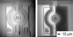
FIGURE 2. In these images of a transistor in an operational amplifier (Texas Instruments µA741), the edges in the one-photon OBIC image (left) are clearly much less sharp than in the two-photon image (right). (Reproduced with permission from Journal of Applied Physics)
For backside one-photon OBIC, another drawback is that electron-hole pairs are generated along the entire length of the laser beam, not just at its focus. This limits spatial resolution and produces a high background signal (poor contrast). Ideally the technique requires a laser that is transmitted by the silicon substrate layer but that is absorbed and produces charge carriers in the doped layers of interest.
Lucent Technologies' Bell Labs (Murray Hill, NJ) researchers Chris Xu and Winfried Denk have demonstrated that two-photon OBIC (2P-OBIC) avoids these limitations by relying on absorption of two long-wavelength photons to produce each electron-hole pair.4 Explains Xu, "In 2P-OBIC, the excitation wavelength is chosen so that the photon energy is below the silicon bandgap (1.12 eV), thereby virtually eliminating one-photon absorption. A high-NA focusing objective ensures that two-photon absorption occurs efficiently only at the beam focus, and the use of ultrafast excitation pulses maximizes the two-photon signal, relative to any residual one-photon effects."
Xu notes that the technique provides improved lateral resolution over 1P-OBIC. "With silicon solid immersion lenses this could eventually provide resolution sufficient for imaging even state-of-the-art, submicron features produced by the latest deep-UV lithography methods," he says
The excitation source for this work is a tunable optical parametric oscillator (Opal; Spectra-Physics) that produces a stream of ~120-fs pulses with an 80-MHz repetition rate (see Fig. 1). Its tunability allows the investigators to optimize the excitation wavelength, which varies according to the amount of doping in the semiconductor being imaged.
Before imaging, the backside of a silicon chip is exposed by grinding away the plastic packaging material and die attach; it is then polished. The beam is scanned using a pair of galvanometer mirrors, and a tight focus is achieved by filling the full 5-mm aperture of a 40X oil immersion objective lens (Zeiss).
Both memory chips and operational amplifiers have been imaged in this way. In the case of memory chips, the OBIC signal is observed as a variation in the supply current. With an operational amplifier the image is recorded as a change in the inverting bias current as a function of the beam position. Depending on the features scanned, these contrast signals may be positive (light) or negative (dark).
A comparison of 1P-OBIC and 2P-OBIC images of an operational amplifier (µA741;Texas Instruments) shows the superior contrast and resolution of the two-photon images (see Fig 2). When examining submicron features, such enhanced resolution would be critical.
Xu points out that this new technique also could have significant application in optoelectronics. "With integrated devices of increasing complexity, such as advanced laser diodes and vertical-cavity surface-emitting lasers, there is a developing need to probe the relationship between structure and function. High-resolution imaging techniques such 2P-OBIC can provide just such information."
THG imaging of films and interfaces
Imaging of transparent objects, such as glasses and uncolored biological materials, has long presented a challenge to optical microscopy. Traditional imaging methods, including phase contrast microscopy, rely on changes in refractive index. Recently, Yaron Silberberg and coworkers at the Weizmann Institute of Science (Rehovot, Israel) have demonstrated that THG can be used to produce high-resolution, 3-D images of transparent interfaces.5 The technique was extended by Jeff Squier and Kent Wilson at the University of California, San Diego (UCSD) with their collaborators at the BioCentrum Institute for Molecular Cell biology (Amsterdam, The Netherlands).6 This novel THG imaging technique has the potential to image such disparate objects as optical fibers, thin films, and biological membranes.
Second-harmonic generation (SHG) based on a tightly focused laser beam previously had been investigated as the basis for microscopic imaging by several researchers, but SHG is limited to noncentrosymmetric materials such as crystals or structured media. In contrast, THG has universal applicability because all materials have a nonvanishing third-order coefficient.
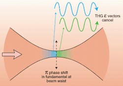
While a full mathematical explanation of this technique is rather complex, the underlying principles are relatively straightforward. When a beam of coherent light is focused to a small spot or line, all materials have the potential to generate light at the third-harmonic frequency. Explains David Fittinghoff of the UCSD group, "As a result of the tight focus, THG only occurs within one confocal length (or less) on either side of the actual beam waist. But the fundamental beam undergoes a phase shift (pi) as it passes through the focus. Thus, the third harmonic generated after the beam waist is exactly 180° out of phase relative to the third harmonic generated in the converging part of the beam" (see Fig. 3).
Continues Fittinghoff, "In a continuous, homogeneous medium, these two components are of equal intensity, so they completely cancel out. If, however, the beam waist occurs near the interface of two materials having different third-order susceptibilities, then the THG intensities on either side of the beam waist are no longer the same and do not exactly cancel out. Likewise, a refractive-index difference at the interface changes the phase shift from 180°, so that complete cancellation does not occur. All real-world material interfaces satisfy one or both of these conditions and thus give rise to a measurable THG component."
FIGURE 3. In a homogeneous sample the intensity of the third-harmonic generation (THG) sums to zero, because the THG radiation generated on either side of the beam waist is exactly out of phase.
The experimental setup for THG imaging is very similar to other multiphoton imaging techniques. In this case, the beam is focused into the sample, and the signal is detected as forward-scattered, third-harmonic light. This is separated from the excitation wavelength using dichroic filters. Cross sections and 3-D images are built up by scanning the focused spot relative to the sample.
Both research groups required ultrafast pulses at wavelengths beyond 1 µm to obtain these images. The Israeli group used an ultrafast OPO, the San Diego group an OPA system. Longer-wavelength excitation is preferred because it facilitates collection and detection of the THG (at 400 nm for 1.2-µm excitation) signal. Furthermore, longer wavelengths minimize damage in biological samples.
FIGURE 4. Repeated optical sectioning of a plant leaf using third-harmonic-generation imaging shows no photobleaching. This image was reacquired every five minutes for one hour, with no observable fading or structural change. (Reproduced with permission from Journal of Microscopy)
THG imaging has already been successfully demonstrated with several different types of transparent samples including glass fibers, oil films, and biological samples. In the case of biological samples, it is an adjunct technique to the well-established multiphoton fluorescence method.
When is THG preferable to conventional two-photon fluorescence for biological samples? Says Fittinghoff, "The main advantage of THG imaging is the lack of photobleaching and other photochemistry. Even with two-photon imaging, a fluorescent sample fades with repeated exposure to the excitation beam. With THG imaging, live samples can be imaged continuously over several hours without any degenerative effect on the sample or image" (see Fig. 4). Furthermore, he says, "the THG signal is very bright, so that signal shot noise is not an issue. Fluorescence confocal imaging must often be performed slowly, but there is no reason why THG images cannot be acquired at video frame rates."
The maturation of ultrafast laser sources has allowed multiphoton fluorescence imaging to rapidly shift from a novel effect to a powerful method for acquiring high-resolution images of biological samples. With the addition of ultrafast optical parametric devices at longer wavelengths, several new multiphoton techniques have emerged. The new generation of compact ultrafast sources will allow these new techniques to undergo similar rapid growth and diversification.
REFERENCES
- W. Denk, J. H. Strickler, and W. W. Webb, Science 248, 73 (1990).
- See, for example, G. J. Brakenhoff et al., J. Microscopy 181, 253 (1996); J. Bewersdorf, R. Pick, and S. Hell, Opt. Lett. 23(15), 655 (1998).
- S. Hell et al., Opt. Lett. 23(15), 1238 (1998).
- C. Xu and W. Denk, Appl. Phys. Lett. 71(18), 2578 (1997).
- Y. Barad et al., Appl. Phys. Lett. 70 (8), 922 (1997).
- M. Muller et al., J. Microscopy 191(3), 266 (1998).
BRUCE CRAIG is marketing manager at Spectra-Physics Lasers, 1344 Terra Bella Ave., Mountain View, CA 94043; e-mail: [email protected].
