Optical Materials: Silicon carbide mirrors benefit high-speed laser scanning

KEVIN F. CARR
The latest high-speed laser scanning systems are quickly being adopted for printing, cutting, welding, drilling, and various other applications that require scanning of a laser beam. The main performance drivers for these scanning systems are scan speed and laser output power. After providing a laser of sufficient power, scan speed is determined primarily by the material and design of the scan mirror. Lightweight silicon carbide (SiC) mirrors offer clear advantages over alternatives such as glass or silicon mirrors, including high stiffness and high thermal conductivity—ideal for dynamic optomechanical systems. The key overall benefit of using SiC mirrors is the ability to increase the scan rate and consequent productivity of the tool in which the scanner is used. System throughput is a critical performance factor that drives the price of these products.
Historically, beryllium mirrors have provided the stiffness-to-weight ratio desirable for low-inertia, fast-scanning laser systems. For both high laser power and high scan speeds, beryllium mirrors offer three times faster scan speeds than, for instance, fused-silica mirrors. However, only a few optical fabricators make beryllium mirrors, primarily because the toxicity of the metal poses a risk during fabrication that requires special effort and higher operating costs to comply with environmental and industrial regulations. In addition, special optical coatings for high-power lasers are required for beryllium mirrors, and coating suppliers are just as scarce. Moreover, the supply of mirror-quality beryllium is limited for commercial applications. Its primary use is in optics for aerospace and defense, and it is therefore considered a strategic material controlled by the National Defense Stockpile. Long lead times for beryllium scanner mirrors are common.
Silicon carbide can replace beryllium in high-speed laser scanning systems without lowering dynamic performance. It is a polycrystalline ceramic and makes an ideal mirror substrate material. Silicon carbide offers high hardness, high strength, and high thermal conductivity—characteristics that are superior to alternatives such as glass, glass-ceramics, and metals that are often used for reflective optical systems. And unlike glass and glass ceramics, SiC can be formed into complex 3-D structures, allowing efficient manufacture of integrated optomechanical assemblies and ultra-lightweight components.
An ideal application for SiC mirrors is replacement of the beryllium mirrors used in high-speed microvia laser drilling tools. Microvias are extremely small through-holes drilled in adjacent layers on very densely packed printed circuit boards (PCBs). Such tools must be able to drill thousands of vias per second, and their value is measured in kilovias per second per dollar. For microvia laser drilling tools, final delivery of finished goods worth $500,000 often cannot be completed when waiting for beryllium mirrors worth $1,000 to finish final system checkout.
Smaller spot size
In a galvanometer scanner, both maximum scan frequency and acceleration is dependent on the mirror inertia. The mirror weight and moment of inertia must be minimized. Most galvanometer mirrors can simply be made as small and thin as possible. The shape of the mirror is determined by the diameter of the laser beam and the maximum scan angle. The mirror clear aperture must fully intercept the beam at all angles. The optimal mirror shape is often a rectangle with corners removed or a more exotic asymmetrical design.1
Galvanometer scan heads contain an x-y mirror pair mounted on rotary motors. Scan heads are typically designated by the beam aperture diameter for which they are intended. A 10 mm scan head, for example, is designed for use with a 10 mm laser-beam diameter over its range of scan angles. Larger beam apertures require larger scan mirrors. A laser scanner system uses a laser beam expander before the scan head, and most often a telecentric objective lens (or f-theta lens) to focus the scanned laser beam onto the work surface (see Fig. 1). The beam aperture of a scan-head design correlates to the focused spot size that the scan head can generate for a given objective lens. According to scan-lens theory (diffraction limited) the focused spot size is inversely proportional to the input beam diameter. In other words, larger beam apertures will produce smaller focused spot sizes, as especially needed for drilling and cutting applications. The benefit of SiC mirrors now becomes clear: to provide larger scan mirrors that support both faster scanning and smaller focused spot size.
Possibly the largest beam aperture supported from a commercial galvanometer scan head is 50 mm diameter. Silicon carbide mirrors offer an optimal solution for high-speed scanning in a 50 mm scan head. The classic galvanometer mirror is a first surface mirror of uniform substrate thickness, a solid slab design. Silicon carbide has the inherent stiffness required for high-speed scanning, but the density of the material will produce a mirror that has too much mass if sufficiently thick to maintain its shape at high-speed rotation. The corners can be trimmed to reduce the mass of the mirror, but further weight reduction is necessary.
It is a common practice in the fabrication of large precision mirrors to remove material from the back side of a substantially thick substrate to reduce mass. Common lightweighting practices of machining large bore holes in the back of a thick substrate are inadequate for galvanometer mirrors. In the case of one optimized light-weighted x mirror, a unique rib design is added on the backside (see Fig. 2). This mirror has a face sheet thickness of less than 1 mm but its performance at high-speed rotation matches that of a 5-mm-thick solid design.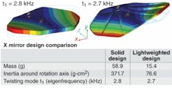
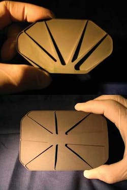
In the case of the corresponding y mirror design for the 50 mm scan head, the light-weighted design reduced its mass by 70% and rotational inertia by 80% (see Fig. 3). For this particular scan system, the y mirror is not required to scan at a speed as high as the x mirror. The eigenfrequency boundary for the y mirror is a minimum of 1 kHz.
REFERENCES
1. D. Collier and R. Schuster, Laser Focus World, June 2006; www.laserfocusworld.com/articles/257231.
2. H.D. Vargas, ed., “Design Guide: Fabrication of Silicon Carbide Parts,” from Poco Graphite, Inc., December 2006.
At the time of this writing, KEVIN F. CARR was the Director of Optics Business Development at RAPT Industries, Inc. 46535 Fremont Blvd., Fremont, CA 94538; www.raptindustries.com. He is currently vice president, sales and marketing, at B&W Tek, 19 Shea Way, Newark, DE 19713; e-mail: [email protected]; www.bwtek.com.