NULL OPTICS: Approaches to aspheric metrology become more diverse
Gary Devries and Andrew Kulawiec
Null optics allow mild to strong aspheres to be interferometrically tested. As an alternative, subaperture-stitching interferometry measures mild to moderate aspheric surfaces without the need for null optics.
In today’s optics industry, aspheres are becoming more common as demand grows for smaller, lighter, and less expensive optical systems. As a rule of thumb, adding one aspheric surface can replace two spherical surfaces when designing an optical system. This is possible because aspheres afford more degrees of freedom that can be used to optimize system performance. But while spherical manufacturing is relatively simple and well established, asphere manufacturing can be quite challenging.
Metrology in particular is a significant bottleneck in the cost-effective production of aspheres. To extend interferometric metrology techniques from spheres to aspheres, additional nulling optics are typically required. Setting up null optics is often difficult and time-consuming, and they are usually applicable only to a specific asphere prescription. These factors restrict the use of aspheres to very expensive or high-volume applications, and limit the utility of aspheres for more “mainstream” applications. An alternative method using subaperture-stitching metrology is now available that eliminates the need for null optics for testing of mild to moderate aspheres.
Aspheres and interferometry
The most common and precise means for measuring optics is interferometry. A “perfect” measurement in interferometry is one in which the difference between the reference and test wavefronts can be reduced to contributions from the test wavefront only. High-density fringe fields, imaging distortion, and reference-wave error are factors that limit measurement accuracy. However, selecting the correct measurement configuration can mitigate these error sources.
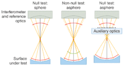
In a null configuration, the reference and test wavefronts are nearly identical. Null measurements are desirable because they inherently minimize fringe densities, ensuring that the majority of the interferometer optics are “common path.” Interferometer optics that are common path are advantageous because both the test and reference wavefronts are affected in the same way, rendering a net zero effect on the difference. In spherical measurements a null is easily achieved. Using just a few reference optics (for example, transmission spheres for a Fizeau interferometer), interferometers generate spherical wavefronts that can be used to test a wide range of spheres. A general-purpose null setup for aspheres, however, is elusive since aspheres lack the point symmetry of spheres. When tested like spheres, aspheres violate the null condition, introducing fringes and, consequently, retrace errors into the measurement (see Fig. 1).1
The null optics (also referred to as auxiliary optics) are used to conserve the spherical shape of the test wavefront as it returns from the test setup. Adding null optics to the test makes the measurement more difficult. Their contribution to the test wavefront must be sufficiently known so that errors in the final measurement can be completely attributed to the asphere under test. For any given asphere, a number of auxiliary optic configurations can be used, but in general the configuration will only apply to that asphere design. Other aspheres would require a different null configuration. Minimizing the number of parameters necessary to configure a null test reduces complexity and hence overall measurement uncertainty.
Aspheric null measurements
Aspheric interferometric null tests can be classified into three main classes: conic, refractive, and diffractive.
Conic sections are conveniently tested using a spherical reference. Conics are defined by two specific points, optically equivalent to stigmatic image points, known as conic conjugates. The purpose of null optics is to either image one conjugate onto the other or back onto itself. Using auxiliary optics to image these conjugate points assures that a null measurement is conserved (see Fig. 2).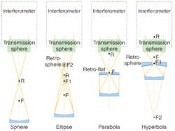
In each aspheric case, a single auxiliary null optic is required in the test, and the optical surface is measured in a double-pass configuration. Hindle used auxiliary spherical optics to form stigmatic images of the conjugate foci of hyperbolae or ellipses.2 Silvertooth later extended Hindle’s method to testing concave hyperboloids as well.3 These tests have distinct disadvantages in that the null optics are typically of equal or greater size than the test optic, they must be precisely aligned, they pertain to only one asphere, and they apply mostly to concave optics. Additionally there is almost always a central obscuration. Although conics are valuable in improving on-axis system performance, not all systems can benefit from this class of asphere. In order to address the needs of all rotationally symmetric optical systems, a test setup for the general class of rotationally symmetric aspheres is needed.
Refractive nulls can be used to test any rotationally symmetric asphere. Abbe Offner demonstrated how a pair of properly designed refractive elements could be used to test a general aspheric surface at null.4 In this case there is no central obscuration, which is an advantage over a conic null test. It also has the advantage that it uses all-spherical optics, which can be easily made. Refractive nulls can be expensive though, especially when testing large convex aspheres (since they must be larger than the test asphere). The accuracy of refractive nulls is limited by the homogeneity of the glass, how well the optics are fabricated, and the ability to precisely align the optics in the test setup.
Holograms, or diffractive optics, are another kind of auxiliary optic that can be used for an aspheric null test. Holograms can either be optically recorded or generated using various computer-controlled techniques (and are referred to as “computer-generated holograms,” or CGHs). Optically recording holograms are less useful because an aspheric master is required. A computer-controlled method is typically used because fabrication techniques using precision stages can produce both amplitude and phase holograms of sufficient accuracy. Error sources such as substrate error and position uncertainty need to be accounted for to obtain higher-accuracy, low-uncertainty measurements.
Challenges associated with the use of null optics
Obtaining accurate measurements of aspheres using null optics is nontrivial. This is because contributions to the measurement from the null optics are difficult to separate from those from the test asphere. For example, small positioning errors of the null optics are degenerate with the low-order errors of the test asphere. Lateral positioning errors will increase asymmetric error while any position errors along the axis of symmetry add to the spherical-aberration uncertainty. To separate positioning errors from the measurement, they need to be independently measured and compensated.
Null optics are generally dedicated solutions for measuring particular aspheres. For each different aspheric surface, custom design and fabrication of the null optics will likely be required. This may be economically justifiable if a large number of the same asphere is being produced, or if the asphere is of extremely high value (such as with telescope mirrors), but it is not conducive to a flexible manufacturing environment. Furthermore, the lead time associated with the procurement of null optics can be prohibitive. While CGHs are commercially available from several sources at moderate costs and lead times, there are limitations to the maximum sizes and aspheric departures that can be measured. Refractive nulls typically require the user to have extensive capabilities in the design, fabrication, and precision assembly of optical systems.
An alternate approach
Given the challenges associated with the use of null optics in aspheric testing, the industry has long sought the development of a robust and flexible aspheric metrology technology. Such a tool would eliminate the need for null optics and enable the cost-effective manufacturing of aspheres in a greater variety of optical systems. Recent developments in subaperture-stitching interferometry have enabled the accurate measurement of aspheres without the use of null optics.5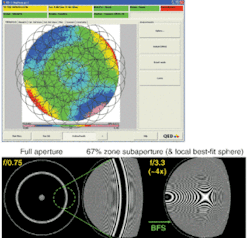
In subaperture-stitching interferometry, a standard Fizeau interferometer is used to collect a number of interferograms covering the entire surface of the optic to be measured. Sophisticated algorithms are then used to “stitch” the interferograms together to form a complete measurement of the surface (see Fig. 3). This method allows for the measurement of mild to moderate aspheric surfaces without dedicated null optics, and also offers the benefit of far greater coverage of large-diameter and/or high-numerical-aperture surfaces. Furthermore, the stitching process provides for greater spatial resolution and improved accuracy through the automated calibration of reference wavefront and retrace errors. Finally, the entire measurement process is automated, thereby reducing the errors associated with improper alignment and setup.
REFERENCES
- G.M. DeVries et al., Frontiers in Optics, OSA Technical Digest (CD) (Optical Society of America, 2006), paper OFWD5.
- J.H. Hindle, Mon. Not. R. Astron. Soc., 91 592 (1931).
- W. Silvertooth, J. Opt.Soc. Am., 30, 140 (1940).
- A. Offner, Appl. Opt. 8, 1735 (1969).
- P. Murphy et al., Optifab 2007: Technical Digest, SPIE Technical Digest TD04, TD040N, (2007) 0277-786X/07/$15 doi: 10.1117/12.719484.
GARY DEVRIES is an optical engineer and ANDREW KULAWIEC is metrology product line manager at QED Technologies, 1040 University Ave., Rochester, NY 14607; e-mail: [email protected]; www.qedmrf.com.