Millimeter waves detect hidden weapons
Weapons hidden on a person's body can be detected using millimeter-wave (subterahertz) radiation; at this wavelength, simple and effective quasi-optical methods can be applied. Quasi-optical methods have a few difficulties, however. The depth of focus of millimeter-wave optics is short and limited by the wavelength, the focal distance, and the lens diameter. If the optics are designed to increase the spatial resolution of the image, the depth of focus will decrease. As a result of the long wavelength, most types of objects in millimeter-wave images appear to have mirror surfaces, reducing the quality of images obtained using a single source and receiver. The conventional type of lens for millimeter-wave radiation is refractive and must be very thick, resulting in large losses in the dielectric lens material; thus, it is very difficult to build a large-diameter millimeter-wave lens.
Almost all of these problems can be successfully solved with the help of diffractive millimeter-wave optics.1–7 A very important advantage of this type of lens is that the focus distance depends on the wavelength of the radiation, so that it is possible to scan the focal plane longitudinally at high spatial resolution to obtain a three-dimensional image with good depth of field.3–5
The depth of field at a single fixed wavelength is small and equal to δγ. When the wavelength is changed using this quasi-optical technique, the focal plane moves by the depth δγ. Each image layer at a different fixed wavelength can contain portions of a target image. The entire three-dimensional target image can then be constructed from the many layers containing separate partial images of a target. By selecting "informative" layers (those that contain a signal from the target), it is possible to decrease the noise in millimeter-wave images and increase the signal-to-noise ratio. In addition, because diffractive optics are inherently thin, it is possible to build large-diameter millimeter-wave diffractive lenses and decrease the energy losses in the lenses' material.
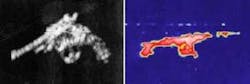
We have used two frequencies—75 and 140 GHz—in two different devices. Although lower-frequency millimeter waves—such as those at 33 GHz—are reflected by the human body as well as by concealed objects, higher-frequency millimeter waves (75 GHz and more) are reflected more by concealed objects than by the human body (see Fig. 1).

null
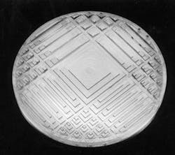
Millimeter-wave diffractive lenses made from polystyrene, polyethylene, or similar materials, and consisting of two identical Fresnel zone plates (FZPs) with a gap between were used in the experiments. Later, we used dual-component curvilinear FZP lenses to increase the field of view. We also used special so-called "X-type" dual-component millimeter-wave lenses to decrease the noise on the millimeter-wave image and increase the diameter of a lens up to several meters (see Fig. 2). In an X-type diffractive lens, the scattering function of a point source is not rotationally symmetric. When we use two lenses, one of which is rotated with respect to the other, the resulting scattering function of a point has reduced side-lobe levels.
null
Using special "isotropic" methods to destroy interference noise and mirror spots on the image result in a millimeter-wave image with quality equal to optical images. These methods reduce the coherence of the radiation—for example, by exposing the target from different directions or receiving reflected radiation from several angles—and are equivalent to using wideband radiation.
For three-dimensional scanning, we used a one-dimensional array of 32 receivers, frequency scanning to change the focus distances of a diffractive lens, and two types of mechanical scanning for the third coordinate—one that exploited the rotation of the target and another that used the motion of the person passing through a controlled passageway.
In laboratory tests with 75-GHz coherent radiation, detailed images clearly show an object (a machine gun) concealed under a moving man's clothing. For scanning in the third axis, the millimeter-wave frequencies in the experimental device spanned a 30% range; 256 discrete sequentially emitted wavelengths within this range were used (equal to 256 images with different focal-plane positions). The depth of field of the control was about 500 mm (limited by frequency deviation and the flat surfaces of the diffractive lens); the field of view was about 650 × 650 mm with 32 pixels on a side (about 20 mm between each pixel) and was limited by the lens and receiver diameters. The lens diameter was 700 mm with a thickness of 10 mm for each lens. The millimeter-wave power on a man's body was within allowable limits for medical devices.
This research began in 1982 and has been published in several Russian books.4–6 The millimeter-wave quasi-optical method is simpler in technical realization than holographic.8
Recent investigation shows that the contradiction between the space resolution and focus depth of classical millimeter-wave optics can also be solved by scanning properties of millimeter-wave diffractive "lens-plus-axicon" lenses and special spiral FZP lenses with long focus. These methods can also be applied at acoustic and terahertz wavelengths.
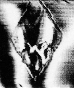
We also studied another simple method of millimeter-wave imaging of a phase object placed on a reflecting surface.5, 6 In this case, we focused millimeter-wave radiation on the plane of interest and superimposed a reference wave on it. From this, the hologram of the focused image could be derived. This procedure requires a mathematical reconstruction, using a specialized computer and software. It is interesting to view a phase object in the hologram (which is actually an interferogram). In one example, a millimeter-wave image reveals a phase target located on a human dummy body and hidden under fabric (see Fig. 3).
null
REFERENCES
- I. V. Minin and O. V. Minin, 50th Vehicular Tech. Conf. VTC 1999-Fall, Amsterdam, The Netherlands, softcover, 1924 (Sept. 19–22, 1999).
- I. V. Minin and O. V. Minin, Proc. SPIE 4129, 616 (July 31–Aug. 3, 2000)
- Laser Focus World 38, 9 (November 2002).
- I. V. Minin, O. V.Minin, Moskow: Diffractional Quasi-optics, InformTei, 180 (in Russian; 1992).
- I. V. Minin and O. V. Minin, Diffractional Quasi-Optics, Novosibirsk: SibAgs, 308 (in Russian; 1999; translated from Russian into English by IOP Publisher).
- Methods and devices for terrorism struggle, Ed. by Prof. V. F. Minin, Novosibirsk State Technical University, 131 (in Russian; 2002).
- I. V. Minin, O. V. Minin, Proc. 25th Int. Conf. IR and mm-waves, Beijing, China (Sept. 12–15, 2000).
- I. V. Minin, O. V. Minin. Accepted for the 6th Int. Symp. Antennas, Propag. and EM Theory, ISAPE-2003, Beijing, China (Aug. 17–21, 2003).
IGOR MININ and OLEG MININ are lecturers and chief researchers at Novosibirsk State Technical University, K. Marksa St., 20, Novosibirsk, 630092, Russia; e-mail: [email protected].