Grating beamsplitters grow in complexity
The diffractive-grating beamsplitter—in its primitive form a binary grating—has evolved in design to become a highly efficient multiphase-level grating that is tolerant of fabrication errors.
Beamsplitters are an ideal application for diffractive optics. The flexibility that is possible in the microstructure surface topography of the optic permits the creation of complex arbitrary patterns in the far field. Beamsplitters have been used for marking and hole drilling for many years. The first diffractive beamsplitters were based on a simple two-phase-level surface topography; now, with better design tools, fabrication techniques, and metrology tools, much more complex, high-quality beamsplitters can be fabricated.
A case study for a hole-drilling application highlights the evolution of diffractive beamsplitters, from devices that produced a one-dimensional line of beams with poor power uniformity, to (after several iterations) a complex, nonsymmetrical, highly uniform power distribution of a two-dimensional array of beams.
Background
Diffractive beamsplitters are formed by etching a very shallow structure of a certain shape into the surface of a transparent material. Diffractive beamsplitters are also referred to as phase gratings, since this shallow structure alters the phase of the incoming wave to produce the desired far-field pattern. The depth of the structure is typically equal to or less than one wave of optical-path difference for a given material at a given wavelength of light. The structure is typically periodic and thus can be modeled by a Fourier analysis.
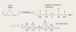
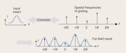
In the mathematical model of the grating, the input beam is convolved with spatial frequency weights defined by the surface-relief structure of the grating. The result is that the input beam is copied to each angular location (diffractive order) and scaled by the weighting of that diffractive order (see Fig. 1).
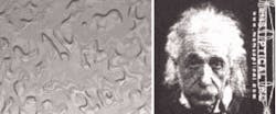
The specific details of the surface topography of the grating can be nonintuitive (see Fig. 2). For this reason, many robust design techniques such as genetic algorithms, simulated annealing, and a variety of direct-search methods have been developed to iteratively arrive at an optimal solution. The result is a phase grating that can produce highly arbitrary patterns in the far field.
The fabrication of these microstructures in the surface of the material can be accomplished in several ways. The most common method is to use a photolithographic step followed by an etching step, as is done in the semiconductor manufacturing industry. The two main variants of the photolithographic method are to use either a series of binary masks to build a stepped multiphase structure, or a single gray-scale mask to create a near-continuous structure. Typically, the gray-scale mask technique produces a higher-quality result with fewer fabrication steps and thus lower cost.
Application
Phase gratings have many uses; one industrial application is hole drilling. By splitting a powerful input beam into many beams, a series of holes can be generated with great accuracy. This simplifies the drilling system by reducing or even eliminating the need for high-precision positioning stages, and increases throughput by drilling all the holes in parallel. Typically, the efficiency of the beamsplitter should be as high as possible (usually greater than 85%), and the nonuniformity of the beams should be as low as possible (usually less than 3%). The efficiency is a measure of the percentage of energy that is present in the desired orders, neglecting any reflection or absorption losses, which are usually quite low when an antireflection coating is used. To calculate nonuniformity, the difference between the maximum and minimum intensities is divided by twice the average intensity.
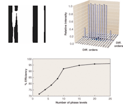
FIGURE 3. A single period of a two-phase-level phase grating shows its binary nature (top left). The resolution of the unit cell that is repeated to make up this periodic grating is 128 by 128 points. The output of this phase grating in the far field in the nine desired orders shows unacceptable levels in the various orders (top right). The diffraction efficiency of a phase grating can be increased by increasing the number of phase levels (bottom). A ten-level optic produces the efficiency that is typically needed for industrial use (note that results are dependent on the desired spot pattern, although the trend is generally consistent for most spot-pattern designs).
An early and simple version of a grating used for hole drilling produced nine equally spaced beams along a line and used only a two-phase-level diffractive beamsplitter (see Fig. 3). The design efficiency of this grating was 71.8% and the nonuniformity was 1.43%. The amount of energy arriving in the desired orders for this early iteration of the diffractive beamsplitter was not acceptable. The efficiency of a grating can generally be increased by increasing the resolution in the depth dimension—that is, by increasing the number of phase levels of the device.
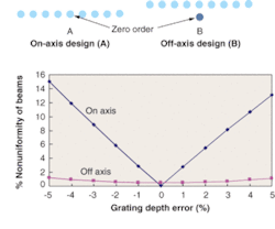
The most recent improvement in the evolution of the diffractive beamsplitter comes from understanding the source of the nonuniformity. Generally, typical fabrication errors have a much more significant affect on the nonuniformity of the beams then the efficiency of the beamsplitter. It was found through many iterations of modeling that the majority of the "noise" from fabrication errors is generally symmetrical about the zero order. If one desires a line of beams that is centered about the zero order, the energy in the desired orders is symmetrical about the zero order. Thus, the desired orders and the noise are coexistent. This causes energy to be added to some orders and subtracted from other orders, causing poor uniformity. The solution is to shift the pattern such that the desired beam pattern is no longer symmetrical about the zero order (see Fig. 4).
To realistically determine the performance of a beamsplitter, it is always useful to alter the design of the grating to represent fabrication errors that are always present in any component. One of the main fabrication parameters is the depth of the grating. An off-axis design permits highly uniform beams to be produced in a fabrication-friendly design. This method is extendable to beam patterns that are not all in a line, and has been demonstrated for nonsymmetrical, complex beam patterns with over 200 beams and measured nonuniformities of better than 3%.
DAVID R. BROWN is a senior design engineer at MEMS Optical, 205 Import Circle, Huntsville, AL 35806; e-mail: [email protected].
