Optical MEMS are more than just switches
All-optical switching seemed such a compellingly logical application for optical MEMS that the two became closely identified during the telecommunications bubble. The collapse of the bubble hit MEMS switches hard—the demand for all-optical switches evaporated along with plans for all-optical networks of tremendous capacity, and technical issues emerged for MEMS switches. High-profile products were canceled, startups folded, and gloom spread.
Yet the prospects for optical MEMS are not really dark, because they have applications reaching far beyond the massive optical crossconnects envisioned as gigantic markets during the bubble. Smaller-scale MEMS switches are attractive for applications such as optical add/drop multiplexers. Optical MEMS also can be used in displays, tunable filters, gain equalizing filters, tunable lasers, and various other applications. Home projection televisions containing optical MEMS are already on the market and more new systems are in development.
MEMS concepts and switches
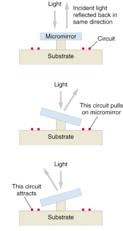
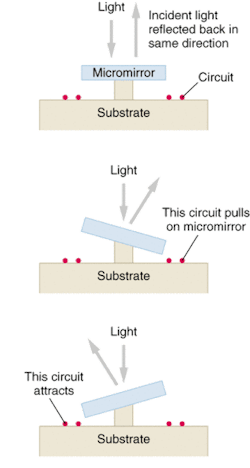
MEMS is an acronym for microelectromechanical systems—microscopic mechanical devices fabricated from semiconductors and compatible materials using photolithographic techniques. Mechanical structures small enough to be flexed over a limited range of angles are chemically etched from layered structures, where they remain suspended above a substrate. Electronic circuits on the substrate control their motion by applying voltages or currents, generating electrostatic or magnetic forces that attract part of the flexible component (see Fig. 1). In the best known optical MEMS devices, the moving components are mirrors that are tilted or moved vertically. Other moving optical MEMS components include microlenses and optical waveguides.
Optical switching typically involves tilting MEMS mirrors to redirect an input beam arriving from above the mirror. The motion can be continuous, or limited to two positions where the mirror latches in place. Continuously tilting the mirror on one axis scans a laser beam in a straight line. Tilt it on two perpendicular axes, and it can scan across a plane. In principle, a two-axis tilting mirror with suitable drivers should be able to direct an incoming beam to one of many output ports in the plane, depending on the angle of the incoming beam and the tilt angle of the mirror. This approach was hotly pursued for optical crossconnects with large numbers of input and output ports, but it requires exacting precision in tilting the mirrors, as well as a healthy market. Development continues, but marketing of large-scale switches is on hold.
Moving the mirror back and forth between two latched positions can only direct the input beam in one of two fixed directions. This is sometimes called "digital MEMS" because the two positions can be considered "off" and "on," unlike continuous tilting "analog MEMS" mirrors that can address a continuous range of points. Switching the mirror between two latched positions simplifies beam alignment and reduces adjustment requirements, but requires many more switching elements to serve large numbers of input and output ports. For that reason, digital MEMS are better suited to low port counts.
Other types of MEMS devices also have been developed. Some direct optical signals by moving microlenses or solid optical waveguides rather than mirrors. Others move arrays of parallel strip mirrors to create diffractive effects.
Tilting mirror displays
Tilting-mirror MEMS have already carved out a healthy market in projection displays, a market pioneered by Texas Instruments using its Digital Light Processing system (http://www.dlp.com). At the heart of the display is an array of up to 1.3 million mirror elements, each hinged to tilt back and forth between two positions. Each micromirror in the array is one picture element in the display. In one position, the mirror reflects input light into the projection optics and the pixel is on; in the other, it reflects light in a different direction, and the pixel is off.
Viewed instantaneously, the result is a pure black-and-white display, with each pixel either off or on. However, the mirrors switch back and forth at up to several kilohertz, turning pixels on and off far faster than the human eye can detect. The human eye averages the light intensity over much longer intervals, so it sees a shade of gray rather than the instantaneous black or white pixel.
Color can be added in a similar way, by passing input white light through a spinning color wheel that contains red, blue, and green filter segments. Each pixel mirror reflects only a single color at any instant, but the eye averages the colors over time, so it perceives a full-color image. The color of each pixel depends on the modulation pattern. If the pixel is switched off every time the light passes through the green filter, the combination of red and blue light makes the pixel look purple. In this way, a projector using a single mirror array chip can display 16.7 million colors (see Fig. 2).
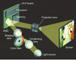
In the one-chip projector, input light passes through focusing optics and the spinning color wheel, which slices it into brief bursts of red, green, and blue. Micromirrors in the "on" position then reflect light from selected pixels through the projection optics, which focus it onto the screen to create an image. To provide the very high brightness and resolution needed in movie theaters and some other applications, projectors are designed with three separate micromirror-array chips, each illuminated by a separate lamp filtered to give one primary color, with the reflected monochrome images combined and focused onto the same screen.
Micromirror displays are among the leading technologies for large-screen and projection home television monitors, because they can offer the high resolution needed for high-definition television. Many models are already on the market, and more are coming. Other image projectors use micromirror displays, including a volumetric three-dimensional display developed by Acuity Systems (www.acuity-systems.com). The arrays also can serve as spatial light modulators for optical signal-processing applications.
Diffractive MEMS
Tilting-mirror MEMS devices scan a fixed-intensity beam, changing its direction but not its cross section. Diffractive MEMS instead change the diffraction pattern of light striking them, changing the angular distribution of the light rather than the direction of a narrow beam. Essentially, diffractive MEMS devices are dynamic diffractive optical elements formed by an array of reflective strips moved back and forth relative to each other.
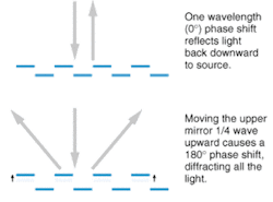
In one design, the array includes two sets of long, narrow refractive stripes, one of which moves relative to the other by up to one-quarter of the operating wavelength (see Fig. 3). In the "off" state, the phase shift between light reflected from the two layers is an integral number of wavelengths, so the reflected waves add constructively, producing peak intensity at the point where light would be reflected directly. At maximum motion, the phase shift is 180°, so the reflective waves add destructively, diffracting the light so the intensity is zero at the point of direct reflection is zero and higher in the first diffraction order.
Diffractive MEMS can be used for switching and display applications, like tilting-mirror MEMS. The moving linear elements can switch between two latched positions, for example; at one all the input light is reflected so the output is "on," but at the other all the input is diffracted, and the output is "off." Sony has developed projection displays based on a linear array of diffractive MEMS elements called a "grating light valve." Sets of six adjacent reflective strips form individual pixels, and each linear array contains hundreds of those six-element pixels, which switch between on and off positions. They reflect light to projection optics that includes a mirror scanning the screen at 60 times per second, creating a two-dimensional image from the illuminated pixels on the linear array. Sony has used it to display progressive scan HDTV at the maximum resolution of 1920 × 1080 pixels.
In addition, diffractive MEMS can perform functions that are more difficult with tilting mirrors and other optical devices, such as tunable filters and differential gain equalizers. In a differential gain equalizer, an optical demultiplexer such as a diffraction grating spreads out the input optical channels along the length of a linear array of diffractive MEMS elements. Groups of several diffractive MEMS strips combine to modulate the intensity of each optical channel. The strips are moved over a continuous range, rather than between two extremes, to modulate the diffraction intensity continuously. This gives the continuous range of attenuation needed for differential gain equalization. Similar principles can be used to design other components in which channels must be modulated or switched independently.
Other applications
Some applications don't fit neatly into the diffractive or tilting-mirror categories. One example is the vertical motion of a MEMS mirror to tune the output wavelength of a VCSEL. Little motion is needed because VCSEL cavities are very short, making MEMS mirrors a natural fit. Similar MEMS mirrors can be incorporated into tunable Fabry-Perot cavities to make modulators. Other applications under development include the use of MEMS elements that move vertically to change the shape of mirrors in adaptive optics. MEMS might be particularly attractive for small adaptive optical elements, such as those used for vision measurement and correction.
Some issues are still being addressed. Although MEMS devices have proved surprisingly resistant to fatigue cracking, care is required to avoid "stiction," in which surfaces remain stuck together after contact. Another important issue is the response to shock and vibration. Because shock generally comes at low frequencies, MEMS with high resonant frequencies, designed for high-speed response, are less affected by shock than those with low-frequency resonances.
Still, the prospects for optical MEMS are encouraging. The bubble diverted much MEMS development toward some markets that never materialized, but plenty of real opportunities remain.
ACKNOWLEDGMENTS
Thanks to Yves Lemaitre, Lightconnect, and Steve Senturia, Polychromix,