OTDM promises higher communications speeds using optical processors
Time-domain multiplexing combines pulses from two or more data streams to create a single data stream at a higher data rate. Traditionally electronic multiplexing circuits process multiple input signals to generate an output at the higher data rate, which is then separated into its components at the receiver by demultiplexing electronics. Optical time-division multiplexing (OTDM) promises to achieve higher speeds by using optical processors to multiplex, process, and demultiplex the signals.
Electronic time-division multiplexing is cheap and easy, but its speed is limited by the electronic circuits available. The commercial state of the art is 10 Gbits/s, with 40 Gbit/s possible using custom high-speed circuits. Optical TDM is not subject to the same speed limits, so it can be extended to higher speeds. In practice, OTDM is too expensive to implement at 10 Gbit/s, and electronics are expected to win out at 40 Gbit/s. Yet optics become more attractive at higher speeds and OTDM may be a practical necessity for generating data rates well above 40 Gbit/s.
So far, OTDM largely has been limited to high-speed "hero" experiments. In the near term, its potential applications are limited to systems that require extremely high transmission speeds, such as high-resolution medical imaging systems or arrays of radio telescopes. In the longer term, OTDM offers an alternative architecture for transmitting large volumes of traffic that current systems divide among many optical channels using wavelength-division multiplexing. The key question to be answered is what blend of TDM and WDM will prove best—whether it's more cost-effective to transmit a few streams of high-speed data on widely separated wavelengths or more streams of slower data on more closely spaced wavelengths.
Types of OTDM systems
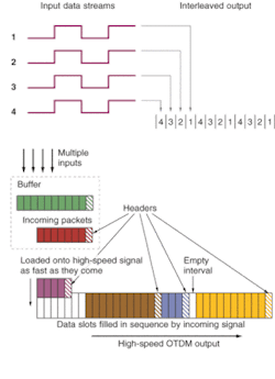
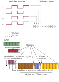
Two fundamentally different types of OTDM systems—interleaved and slotted—have been demonstrated. Interleaved transmission is a logical extension of conventional electronic TDM, in which data bits from separate streams are interleaved one by one. Slotted systems are a type of packet switching in which the system transmits a block of bits from a single data stream, then accepts another block of bits from the same or a different data stream (see Fig. 1). The two types of systems require different architectures.
Interleaving requires shuffling input bits, picking one bit from each input stream, then returning to pick a second bit from each, and so on. This requires slicing and delaying the input pulses, which typically arrive with one pulse per bit interval, so 10-Gbit/s input pulses of 100 ps must be sliced into 25-ps chunks for 40-Gbit/s transmission. They also must be delayed so they enter the higher-speed data stream at the right time. Data bits are identified by their position in the pulse sequence, requiring precise timing on both input and output ends. Optical demultiplexing effectively reduces the raw data rate at the receiver. As with conventional electronic TDM, the output data stream has a slot for every possible bit in each input data stream.
For slotted transmission, input bits must be packaged with a header then transmitted at the higher output speed. Data bits are identified by the packet header rather than by their place in the bit sequence. The receiver must be able to process bits as they arrive at the raw data rate of the high-speed line. As with conventional packet switching, the output data stream does not need a slot for every possible bit in each input data stream because on average each input channel carries less than the maximum possible rate.
Interleaving OTDM requirements
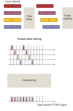
Multiplexing in an interleaving OTDM system involves three distinct functions. The input pulses must be delayed relative to each other by the proper amount (see Fig. 2). Then the pulses are sliced or shortened so they fit into the bit interval of the high-speed signal. In the example of Fig. 2, they are converted from an NRZ (non-return-to-zero) signal spanning the entire bit interval at the lower rate to an RZ (return-to-zero) signal spanning only part of the bit interval at the higher rate. Then the shortened and delayed signals are interleaved to form a single data stream. Key technical issues are precisely controlling the time delays and shortening the pulses to the required lengths.
Other functions are necessary at the receiver for demultiplexing. One is extracting a clock signal that times pulses at the high data rate and can be divided by the number of channels to reproduce the clock signal for the input signals that must be regenerated at the receiver. A variable delay may also be needed. Recovering individual channels also requires a fast optical switch to separate the component signals. Perhaps the most difficult problem is to identify the individual data streams that were combined to make the high-frequency signal.
Add/drop multiplexers have requirements similar to those for receivers, because they need to reconstruct one of the component signals to drop at a point, and must be able to insert a replacement signal into the high-speed data stream. They also require optical "3R" regeneration, which reshapes, reamplifies, and retimes the signal.
Developers are evaluating a variety of components to meet these requirements. Some are fairly simple. Short lengths of fiber or planar waveguide can serve as optical delay lines, to put short pulses into the proper time intervals in the high-speed signal. Some delay lines can be tuned by changing their refractive index to alter the delay.
Fast switches are needed for both slicing input pulses to fit the time slots in the high-speed output and for demultiplexing the high-speed signal at the receiver. Typically the clock pulse controls a switch that turns the data pulse off and on. Several experiments have used electro-absorption modulators, which can attain high speeds but require that the optical control pulse be converted to electronic form. All-optical switching is possible using nonlinear interactions such as four-wave mixing in semiconductor optical amplifiers, which respond at very high speeds. Cross-phase modulation can provide very high-speed switching in a semiconductor optical amplifier placed in an interferometer. Nonlinear optical loop mirrors can achieve even higher speeds, to more than one terabit per second.
Clock recovery is another difficult problem. One approach is to feed part of the received signal into a ring laser that generates modelocked pulses at the clock rate, producing pulses phase-locked to the timing of the input signal. That frequency can be divided for demultiplexing. An alternative is injection seeding a self-pulsating semiconductor laser, in which two detuned DFB sections are separated by an integrated phase-tuning section so the device pulses at a tunable rate.1
One of the trickiest problems is to identify the demultiplexed channels. Each input data stream can be tagged with a radio-frequency marker signal, but that system works slowly so initial bits are lost. Another is to tag the data streams with distinct markers, but again some data bits are lost.
Slotted-transmission OTDM
Slotted-transmission OTDM has different operational requirements because it transmits blocks of input data from one source at a time, rather than continuously interleaving bits from multiple sources. The ultimate goal is to process data from multiple sources, but so far most demonstrations have transmitted packets from only a single input. With multiple possible inputs, this requires a buffer memory to queue packets that arrive while another packet is being sent. Optical delay lines are currently the leading approach for optical buffering, but alternatives are being studied.2
One approach to slotted transmission involves inserting groups of eight data pulses in a slot between pairs of system clock pulses sent at 12.5 Gbit/s (see Fig. 3). The first data blocks are the header; the later blocks are the data payload. In experiments at MIT Lincoln Laboratory (Lexington, MA), the technique was used to transmit pseudo-random data at 100-Gbit/s.3 This architecture requires a transmitter able to generate pulses of only a few picoseconds that can fit into the bit interval.
In the Lincoln system, headers are marked by removing a clock pulse. High-speed processing is needed at the receiver end to recover the clock, read the header, and then switch the packet to the proper output. However, this approach avoids the need to recognize individual channels.
Outlook
Optical TDM developers face tough challenges to demonstrate the performance they need at high speeds. Fast switching and clock recovery are challenges for any type of OTDM. Interleaving also requires a way to identify channels for demultiplexing, as well as adjustable delays to properly time the pulses. Slotted OTDM requires ways to queue input packets and to process headers.
Nonetheless, some impressive demonstrations have been reported. Many groups have interleaved four 40-Gbit/s signals to generate 160-Gbit/s data streams, and a few have gone the next step to reach 640 Gbit/s. The OTDM record seems to be 1.28 Tbits/s, generated at Tohoku University in Japan, and transmitted 70 km using solitons and advanced dispersion compensation.4 Slotted transmission has been demonstrated at lower speeds.
The biggest question is what technology will prove the best way to optimize fiber transmission capacity. In a general sense, a single 160-Gbit/s data stream theoretically requires as much bandwidth as four 40-Gbit/s streams or sixteen 10-Gbit/s data streams. The trick will be to find the combination of TDM and WDM that gives the most cost-effective performance. Interesting work is being done on balancing the two, and the answer is likely to depend on the installed fiber base.5 Stay tuned.
ACKNOWLEDGMENTS
Thanks to Scott Hamilton, MIT Lincoln Laboratory, and Erwin Bente, Technical University of Eindhoven.
REFERENCES
- Mohrle et al., IEEE J. Sel. Topics Quant. Electronics 78, 217 (2001)
- Y. Li, et al, IEEE Photonics Tech. Lett.14( 6) 849 (June 2002).
- S. Hamilton et al., J. Lightwave Tech. 20, 2086 (December 2002)
- M. Nakazawa et al., Electronics Lett. 36, 2027, (2000); also presented as postdeadline paper 2.6 at ECOC 2000.
- H. Sotobayashi et al, IEEE LEOS Newsletter, 24 (October 2002).


