Electro-optic displays deliver a feast for the eyes
Electro-optic technologies have long played a starring role in the display of information and images, as evidenced by the ubiquitous television tube. But in an age when information has become a best-selling commodity and images often define an entire product, electro-optic displays have grown even more important than ever.
The information explosion has pumped billions of dollars into the development of new display techniques, and the commercial fruits of those investments are now being enjoyed in products such as laptop computers and wide-screen projection TVs. This article reviews the fundamental technology behind two of the most successful electro-optic displays: cathode-ray tubes (CRTs) and liquid-crystal displays (LCDs).
CRTs were first
The first, and still the foremost, electro-optic display is the CRT. After more than a century of development, CRT technology has reached a high art, and it is likely to dominate the display market for a long time to come.
The development of CRTs began around 1880 when the British scientist William Crookes (1832-1919) constructed a special vacuum tube to investigate the nature of cathode rays (see Fig. 1). Crookes found that cathode rays would cast sharp shadows on a fluorescent screen when they encountered an obstruction and could also be bent in different directions by a magnetic force field. Based on these and other observations, it was soon realized that cathode rays consisted of a stream of negatively charged particles called electrons.
In 1897, Karl Ferdinand Braun (1850-1918) perfected the Crookes tube into the first working oscilloscope by adding a phosphor-coated fluorescent display screen and two sets of electrically charged plates to deflect the electron beam vertically and horizontally. Braun`s oscilloscope became the forerunner of today`s CRT display.
A modern monochrome CRT display consists of a heated cathode for thermionic emission of electrons; a control grid to guide the flow of electrons; two anodes to focus and accelerate the electrons into a converging beam (e-beam); two sets of charged deflection plates to sweep the e-beam up, down, and sideways; a phosphor-coated display screen that fluoresces when bombarded by electrons; and a conductive "Aquadag" coating for collecting back-reflected and secondary electrons from the phosphor layer. All of these elements are sealed inside a carefully molded glass tube that is evacuated to a low pressure (see Fig. 2).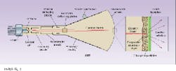
Because image brightness depends on the number and energy of electrons crashing into the phosphor screen, the heated cathode often includes an oxide layer of barium and strontium to enhance free-electron production. The control grid, which consists of a metal cylinder with a hole in one end, is kept at a higher negative voltage than the cathode and would ordinarily stop electrons from passing through the hole if it were not for the high-voltage focusing and acceleration anodes on the other side.
Some of the electrons that accelerate through the aperture of the control grid actually strike the focusing anode and return to the power-supply circuit, but most of them become caught in the electrostatic force field created between the focusing and acceleration anodes, which are set at different potentials. The result is a focused beam of high-speed electrons striking the phosphor screen.
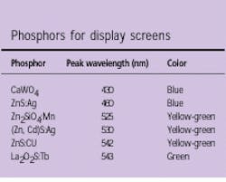
About 10% of the electrons backscatter from the phosphor surface and are swept back into the circuit by the Aquadag coating, which is electrically connected to the accelerating anode. The remaining electrons penetrate the phosphor surface, generating secondary electrons and light. The light produced by electron bombardment, called cathodoluminescence, depends on the type of phosphor used (see table above). Some phosphors emit light of relatively pure color, while others radiate over a wide spectral band and appear white to the human eye. However, the use of a single phosphor defines a monochrome CRT, even if the phosphor emits "white" light composed of a wide range of colors.
A typical monochrome CRT screen consists of a 5-µm-thick layer of phosphor powder applied to a glass faceplate and backed with a very thin evaporated layer of conductive aluminum (see Fig. 2 inset). The aluminum overcoating not only helps reduce charge buildup on the screen, it also boosts image brightness by reflecting a portion of the light back toward the viewer. If the aluminum layer is made too thick, though, image brightness will suffer as the aluminum absorbs more of the e-beam.
The image itself is formed by scanning the focused e-beam spot across the phosphor screen in a raster pattern. The more scan lines used to build up the image, the higher the resolution. In the United States, for example, the standard television format calls for 525 scan lines from top to bottom. In Europe, it`s 625 lines. Light and dark areas of the image are represented by higher and lower e-beam current, respectively.
Moving images are simulated by scanning the whole screen area many times a second, with each full-screen scan representing one "field." To avoid flicker, the full screen should be scanned at a rate of at least 45 fields per second so that the natural ability of the human retina to retain images smooths out the animation. In the United States, the standard video scan rate is 60 Hz, but the fields are interlaced to produce only 30 complete video images, or frames, per second. With interlacing, the odd-numbered scan lines of each frame are usually scanned first, followed by the even-numbered lines. The technique avoids the flicker but uses only half the electronic bandwidth needed for a 60-Hz, noninterlaced frame rate.
Color CRTs
A number of CRT designs have evolved for full-color image display, all of them more complex than monochrome CRTs. The system that has met with the most commercial success is the shadowmask CRT.
Shadowmask CRTs generate a full panoply of colors from a mixture of the three primary colors, which are represented on the display screen by a triad of closely spaced red, green, and blue phosphor dots. The dots are placed so close together that the human eye cannot separately resolve them; therefore, the color mixing actually takes place in the eye, not on the CRT screen. The technique is similar to the process used for color printing, except that the color mixing is additive rather than subtractive.
In a color CRT, then, a single image is made up of thousands or millions of phosphor triads laid down across the display screen. The three phosphor dots of each triad are simultaneously bombarded by three separate e-beams, requiring three precisely aligned electron guns (see Fig. 3). Color balance and brightness are controlled by the electron current of each gun.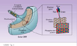
To ensure that each phosphor triad is separately addressed as the three focused e-beams sweep across the screen, a metal shadowmask containing thousands of holes (one hole for each triad) is placed between the electron guns and the screen (see Fig. 3 inset). When the shadowmask is properly positioned, the three e-beams intersect (converge) as they pass through each hole in the mask and separate again just before striking the phosphor triad on the screen. Exact alignment of the electron guns, shadowmask, and phosphor triads is critical to the success of this CRT design.
Two important improvements to the shadowmask CRT include the vertical-stripe shadowmask CRT (see Fig. 4, left) and Sony`s Trinitron (see Fig. 4, right). Both of these CRT designs replace the triad of phosphor dots with three contiguous phosphor stripes that run vertically down the display screen. Vertical resolution is automatically determined by the width of each horizontal scan line.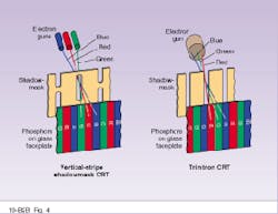
The vertical-stripe shadowmask CRT uses three electron guns arranged horizontally in an in-line pattern, instead of the triangular symmetry of before. Also, the apertures in the shadowmask are slotted instead of round. The Trinitron uses an in-line e-beam configuration as well, but the shadowmask forms an open vertical grill, instead of a series of vertical slots. Both designs simplify e-beam alignment constraints and increase image brightness.
LCDs
Although decades of development have perfected the CRT into a superior display technology, conventional CRTs are bulky, power-hungry devices, which makes them ill suited for many applications that demand low-power, compact, or flat displays. Imagine, for example, a battery-operated laptop computer with a CRT display. For this reason, a great deal of research has been directed toward alternative display technologies, including unconventional flat CRTs. One of the most successful alternatives to the CRT display is the LCD.
All LCDs are essentially spatial light modulators, which means they must be backlit like photographic transparencies. The simplest and oldest type of LCD—the twisted-nematic field-effect (TNFE) LCD—is widely used in alphanumeric displays for watches, calculators, and instrumentation, where information content is low. In these devices, the LCD is small and requires only a few electrode connections to display its information. For example, the typical seven-bar LCD for numeric display uses just eight electrode connections: one for each of the seven bar-shaped cathodes, and one more for the common anode. (For an overview of twisted-nematic spatial light modulators, see Back to Basics, January, 1995, p. 83.)
However, as the resolution or size of an LCD increases, the number of electrical connections can quickly get out of hand if each electrode is separately connected to a voltage source. A 100 × 100 array of LCD electrodes, for instance, would require 10,000 connections. Directly addressing that many electrodes becomes a nightmare, which is why LCDs and other types of displays with a large number of individual picture elements (pixels) use matrix addressing instead.
Matrix addressing dramatically reduces the number of connections by linking the pixels together in an x-y pattern (see Fig. 5). With this configuration, a 100 × 100-pixel array would require just 200 connections to address, but images must be scanned onto the array one row (or column) at a time.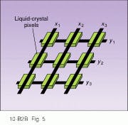
To scan the top row of pixels in Fig. 5, for example, connection y1 is first set at a voltage V just below threshold, which is the point at which the pixels turn on. All other row connections (y, y2, y3, etc.) remain at 0 V. All of the column connections (x1, x2, x3, etc.) are then simultaneously set at either -V or V, depending on whether the corresponding pixel is to remain off or be turned on. The next row is scanned in a similar fashion by biasing y2 near threshold and applying a whole new set of -V and V column voltages. This whole image-scanning process is referred to as multiplexing.
For multiplexing to work properly, each pixel of the matrix should operate as a bistable device. That is, there should be a clear threshold point between on and off states. In addition, each pixel should quickly reach its full on state (saturation) at twice the threshold voltage. Although some electro-optic devices such as light-emitting diodes come close to meeting these ideal characteristics, most LCDs do not.
To begin with, a simple TNFE LCD is not a bistable device and therefore has an ill-defined threshold. Furthermore, each pixel reacts rather slowly to the root mean square (rms) of the addressing voltage rather than the peak voltage. Another problem is that each pixel begins to relax immediately after it has been addressed. Together, these factors lower the contrast of the display and limit the number of lines that can be scanned.
Nevertheless, other liquid-crystal materials have been developed that improve the performance of multiplexed arrays, such as super-twisted-nematic (STN) LCDs and surface-stabilized ferroelectric (SSF) LCDs. Both types have faster response times than TNFE displays, which allows more lines to be scanned. SSF LCDs, though, are also bistable, which boosts contrast.
But one of the most effective approaches to multiplexed LCDs is the active-matrix LCD (AMLCD). The AMLCD circumvents some of the limitations of a passively addressed LCD by forcing it to act more like the ideal pixel matrix described above. Specifically, each pixel of an AMLCD contains an active electronic element that switches and holds the voltage on the pixel until the entire matrix can be scanned.
An especially elegant AMLCD design uses an array of thin-film transistors (TFTs) and capacitors to switch and hold the liquid-crystal pixel voltages. The whole TFT array is fabricated on a transparent glass substrate (see Fig. 6). Since the structure must pass light, opaque metals and semiconductor materials are placed along the periphery of each pixel and the electrodes are fabricated from transparent ITO (indium tin oxide). A patterned layer of color filters is used for full-color display, and the whole structure is sandwiched between the requisite crossed polarizers.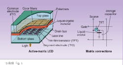
The fabrication of large-area TFT arrays on glass is a delicate and complicated process, yet it has been perfected to the point where 10.4-in. AMLCDs for laptop computers have become routine and larger displays are possible. Moreover, the color performance of AMLCDs can even rival that of CRTs.
In the Information Age, CRTs and LCDs have clearly become the dominant display technologies. Examples of each can be found literally everywhere. There are LCDs for large-screen projection TV as well as miniature monochrome CRTs for helmet-mounted displays (see Back to Basics, May, 1995, p. 131). But there are also plasma display panels for wall-mounted TVs, electroluminescent displays for medical instrumentation, vacuum fluorescent displays for dashboard gauges, and LED displays for digital alarm clocks. These and other electro-optic technologies under development should make the Information Age a little easier on the eyes, if not the mind.
FURTHER READING
Sol Sherr, Electronic displays, 2nd ed., John Wiley & Sons, New York, NY (1993).
Mohammad A. Karim, ed., Electro-optical displays, Marcel Dekker, New York, NY (1992).
Joseph A. Castellano, Handbook of display technology, Academic Press, San Diego, CA (1992).
J. Wilson and J. F. B. Hawkes, Optoelectronics: an introduction, 2nd ed., Prentice Hall, New York, NY (1989).
About the Author
Thomas V. Higgins
Contributing Editor
Thomas V. Higgins was a contributing editor for Laser Focus World, covering science and technology.