Iridium thin films reflect x-rays from AXAF optics
Iridium thin films reflect x-rays from AXAF optics
G. T. Johnston, R. E. Hahn, and A. J. Longmire
Tight tolerances for contamination, oversized coating facilities, and complex handling equipment make coating the AXAF mirrors a challenge.
The Advanced X-ray Astrophysics Facility-Imaging (AXAF-I) is the third of NASA`s four Great Observatories. Slated for launch in late 1998, it is designed to explore the universe over a broad range of x-ray wavelengths. The observatory is currently about mid-way through construction. All of the individual mirror elements have been successfully ground, polished, and tested at Hughes Danbury Optical Systems (HDOS, Danbury, CT). Deposition of the x-ray-reflective coating, scheduled for completion in early 1996, is currently being performed by Optical Coating Laboratory Inc. (OCLI, Santa Rosa, CA). This will be followed by telescope assembly at Eastman Kodak Co. (Rochester, NY) and x-ray testing. Finally the telescope will be integrated into the spacecraft and readied for launch by AXAF-I prime contractor TRW (Redondo Beach, CA).
Design and requirements
The AXAF-I is made up of four concentrically nested Wolter-I grazing-incidence telescopes (see Laser Focus World, Feb. 1995, p. 73). Each telescope consists of two mirrors: a paraboloidal section of revolution followed by a hyperboloidal section of revolution. They combine to form an imaging pair with a focal length of 10 m.
The mirrors are fabricated from Zerodur, a glass ceramic with a negligible coefficient of thermal expansion over the planned telescope operating temperature range. All mirror elements have identical lengths of 84 cm, while their diameters range from approximately 60 cm for the smallest hyperboloid to about 120 cm for the largest paraboloid. The mirror-element thicknesses range from 1.6 to 2.4 cm, and weights range from about 140 to 450 lb.
The sputtered bilayer coating chosen for the AXAF-I mirrors consists of a thin binder layer of chromium (125 Å nominal thickness) overcoated with a slightly thicker iridium layer (300 Å nominal thickness). Due to its relatively high atomic number and its very high density, iridium provides good reflectance at x-ray wavelengths. In addition, the iridium film is quite inert and does not readily form an oxide on its surface. The chromium/iridium combination also forms a mechanically robust coating in comparison to other commonly used x-ray reflective films such as gold.
Requirements for the coating are defined for the highest-energy x-rays (8.04 keV) and specify reflectivity greater than 0.82 at a 20-arc min grazing angle and greater than 0.50 at 34 arc min. Because they function at very short x-ray wavelengths (0.15 to 12.4 nm), the mirrors must not only be precisely figured but must have very low surface microroughness. The as-measured postpolish surfaces met requirements and had microroughness on the order of 4 Å rms. To preserve the enhanced high-energy performance offered by these surfaces, the coating requirements specify that the chromium/iridium thin films add less than 1 Å of roughness.
Contamination control is of paramount importance for the telescope. Coated-mirror fractional area coverage from particulates is called out as less than 1 ¥ 10-5. Upon delivery of the mirrors for installation into the telescope assembly, the maximum allowed thickness of the organic contaminant layer atop the coating is 10 Å. The coating must also pass tape-adhesion tests (MIL-STD-48497) before and after single- and multiple-temperature cycling. All coating performance parameters are verified on witness samples coated at the same time as the mirror elements.
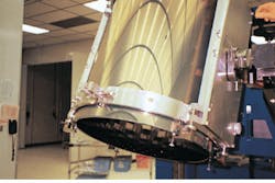
Strict fracture-control requirements limit the maximum tensile stresses that can be imposed on the mirrors throughout their processing and shipping. This necessitated the design of sophisticated handling equipment for all phases of the processing at OCLI (see photos at left and below).
The door-to-door process
In a typical coating cycle, after receipt at the OCLI facility, a mirror element is uncrated and transported into a 2700-sq ft Class 100 cleanroom facility on a dolly. A lift truck lowers a lifting fixture over the mirror, and six "feet" are slipped into place under its lower end. The mirror is lifted off the shipping container base and transferred to an orientation table where the outer surface is cleaned by hand. The mirror element is thoroughly inspected to verify that no fracture propagation or changes in flaws occurred during transport from HDOS.
A handling fixture is next attached to the mirror element. The fixture consists of two elastomer-lined compression bands near the ends of the mirror element, joined on opposite sides by bridging structures to which trunnions are attached (see Fig. 1). All handling operations and operations with subsequent processing equipment are accomplished via the trunnions, avoiding unnecessary direct contact with the glass elements. Experience with previous large-optics coating projects has shown that the single interface method is the most cost-effective, least risky approach.
For cleaning, the mirror element is transported by lift truck to the full-scale cleaner where the mirror element is mounted on a rotary table. A mast containing a series of spray nozzles and a rotating polyvinyl alcohol swab is raised up inside the mirror element. The mirror surface is cleaned under semi-automatic control with a combination of deionized water rinses and an aqueous-based detergent solution. The rotating swab contacts the inner surface of the mirror element during certain segments of the process to provide adequate shear forces for efficient particle removal. Mirror cleanliness is verified by visual observation of the sheeting of rinse water from an overhead spray in the full-scale cleaner. Zerodur witness samples are cleaned in a subscale cleaner using the same method as for the full-scale version. Surface particle analysis has shown that both cleaners can consistently achieve mirror fractional area particulate coverage two orders of magnitude better than the requirement.
After air drying, the mirror is transferred to the coating station and mounted on a rotary table inside the 10-ft-diameter, 7-ft-tall vacuum chamber. The table, sputter sources for the chromium and iridium, and a mechanism to lift the sources in and out of the top of the chamber have been retrofitted onto an existing facility. Witness samples for reflectance, environmental/durability measurements, and contamination monitoring are loaded into special fixtures located above and below the mirror element.
The source assembly, including 66-in.-long chromium and iridium planar magnetron sputtering sources, is lowered into place inside the mirror element. The coating chamber is pumped to high vacuum using cryopumps to minimize contamination. A mass flow meter admits argon gas into the chamber to a pressure of 2 mtorr, and the chromium and iridium layers are sputtered onto the inside of the rotating mirror element. The rotation speed and the deposition rate are chosen such that the mirror element makes at least 30 revolutions during the deposition of each layer; this minimizes any abrupt azimuthal changes in coating thickness at the beginning or end of the layer.
After coating, the mirror is inspected and two ground wires are attached to two coated pads on one end of the mirror element to prevent buildup of static charge. In a Class 100 cleanroom packaging area, the mirror is loaded into a vibration-isolated, nitrogen-purged inner shipping container with specially designed mirror-stabilizing elements and accelerometers. The inner shipping container is placed in an outer container and loaded onto an air ride trailer for transport to Eastman Kodak.
Contamination control and process scale-up
The greatest challenges in the AXAF-I coating program have been mirror cleaning and contamination restriction before and after the coating process. Particular attention was directed to the facility and tooling. Combinations of techniques were developed for cleaning the various pieces of process hardware, including handling equipment, the coating station, and the cleaning stations themselves.
Cleanliness in the coating chamber is maintained by a combination of precisely controlled pump and vent rates and special filtration on the chamber vent lines. Silicon wafers coated along with the mirrors provide a straightforward means of monitoring contamination levels during subsequent processing and shipment. Fractional area particulate coverage is determined with a surface particle counter, and organic layer thickness is inferred from evaluation with a variable-wavelength spectroscopic ellipsometer.
Prior to coating the flight optics, a process scale-up phase and a validation phase were conducted using Zerodur witness samples arrayed within aluminum surrogates that emulate the geometry of the flight mirrors (see Fig. 2). Those witnesses were decontaminated in a subscale cleaner using the same cleaning process applied to the flight mirrors. Coated samples have been measured for x-ray reflectivity at 8.04 keV by the Smithsonian Astrophysical Observatory (SAO, Cambridge, MA). All samples coated in the process scale-up phase exceeded the reflectivity specification at this energy. All environmental/durability requirements were met.
Several tests were performed to mitigate technical risk during the coating of the flight mirrors. During some process scale-up runs, the coating was intentionally stopped and restarted to simulate the effects of power outage and pumping malfunction. Depending on the circumstances, the coating was either continued to completion or a thin layer of chromium was applied, followed by a nominal-thickness iridium layer. In all cases, the "patched" coatings fully complied with technical requirements.
At this writing, the first flight mirror (denoted P6) has been coated. All technical specifications have been met with significant margins. The coating micro roughness is immeasurable within the measurement error of the TOPO-2D interferometer (WYKO, Tucson, AZ), against a requirement of 1 Å. The coating thickness meets the requirements for all coating-induced figure errors. All environmental/durability specifications have been met.
Perhaps most important to the telescope performance in orbit is the surface reflectivity. The P6 x-ray reflectivity as measured by the SAO at 8.04 keV for a 20-arc min grazing angle is 0.86, compared to the requirement of 0.82; at 34 arc min, reflectivity is 0.57 versus a requirement of 0.50. Says AXAF mirror scientist Leon Van Speybroeck of the SAO, "The x-ray reflectivities of the coating witness samples measured here have exceeded the OCLI specification and approach the values measured in the laboratory for the bulk density material. These excellent results will improve the high energy sensitivity of AXAF and thereby enhance the expected scientific return from the observatory." n

FIGURE 1. Trunnions on the mirror-handling fixture provide universal interface to lift truck and vertical risers of the cleaning and coating stations.
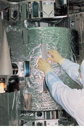
FIGURE 2. The coating process was developed using witness samples arrayed in aluminum surrogates that simulated each mirror geometry. In the mirror-production phase, witness samples above and below the mirror are used for evaluation.
Bulk reprints of all LFWorld articles can be ordered from Sharon MacLeod, reprints manager, Laser Focus World, at (603) 891-9224 or FAX (603) 891-0574.