DIFFRACTIVE OPTICS: Hybrid lenses offer high performance at low cost
GARY BLOUGH and G. MICHAEL MORRIS
Diffractive optics is a technology that provides new and exciting degrees of freedom in the design and optimization of optical systems. Using diffractive optics, one can achromatize optical systems with a single, economical refractive material such as acrylic plastic or common crown glass; create aspheric wavefronts without aspheric surfaces; eliminate the need for exotic and expensive flint-type materials; produce high-performance, large-aperture, lightweight optical components; produce precision micro-optics; and reduce the weight, complexity, and cost of a variety of optical systems.
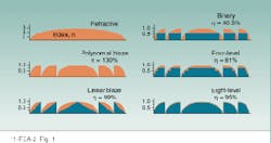
A typical surface-relief diffractive lens consists of concentric annular zones (see Fig. 1). It is useful sometimes to think of a diffractive lens as a `modulo 2` lens: at any given radius along the lens, all of the multiple 2 phase changes in the wavefront of the corresponding refractive lens have been removed. The radius of the mth zone boundary, rm, is defined by
F(rm) = 2 m
where F(r) is the desired phase profile for the lens. These are called full-period zones. In general, the phase function associated with a symmetric lens is given by
F(r) = Ar2 + Gr4 + Hr6 + ...
where A = /(l0F) , l0 is the design or center wavelength, F is the principal focus length of the lens at l = l0, and G and H are associated with aspheric coefficients of the emerging wavefront.
To construct the appropriate surface-relief profile, one starts at the center of the lens, moving radially outward from the center. In general, the surface of the lens is traced until the optical phase difference reaches a value of 2. At that point the surface-relief structure jumps abruptly back to the center height hmax = l0/(n(l0) -1), where n(l0) is the index of refraction of the lens material at wavelength l0. The profile resumes tracing the surface of the refractive lens until the optical phase difference once again reaches a value of 2, at which point the structure returns to height hmax. This cycle is continued until the edge of the refractive lens is reached. The construction process gives rise to a blazed-zone-plate-type structure consisting of a series of zones that represent the required phase transformation. Note that for operation at visible wavelengths, hmax is typically about 1 µm, and zone spacing ranges from tens to hundreds of micrometers.
The spacing of the various zones in a diffractive lens determines the set of possible foci, or diffractive orders, and shapes the emerging wavefront. The blaze profile within each zone determines how the incident light is distributed among these foci. For most applications, the lens designer tries to maximize the amount of light that goes into a given diffractive order (typically the first). Based on scalar-diffraction-theory predictions, one can use a polynomial blaze profile to direct all of the incident radiation at design wavelength l0 into the primary focus, achieving a diffraction efficiency of 100% (see Fig. 1). A linear-blaze profile can produce diffraction efficiencies approaching 99%. A phase-reversal or binary lens directs 40.5% of the incident light into the +1 diffractive order and 40.5% into the -1 diffractive order. Four-level and eight-level approximations to the polynomial phase profile yield diffraction efficiencies of h = 81% and 95%, respectively, in the first diffractive order at the design wavelength.Fabrication of diffractive optical elements
To date, widespread use of diffractive optical elements (DOEs) has been limited by the effects associated with scattered light. Scattering associated with DOEs is classified as either structured or statistical. Structured scattering occurs when light is distributed into unwanted diffractive orders, while statistical scattering refers to random scattering caused by surface roughness.
To produce a surface-relief DOE, a precision surface-relief master element is fabricated and used to create large quantities of replicas. Tooling costs for surface-relief DOEs are similar to those found with plastic-injection-molding processes; cost savings are achieved through replication or molding. With a suitable process, one can manufacture tens of thousands of elements based on a single master.
High-quality DOEs are produced by shaping or micromachining the required surface profile into some substrate material. To achieve high diffraction efficiency, the edge step at each zone boundary has to be extremely sharp and the surface profile within each zone must be smoothly shaped, or blazed, to avoid statistical scattering. The need for sharp edges and smooth blazed surfaces places stringent and somewhat incompatible requirements on the fabrication processes used to make the surface-relief master.
The primary methods developed to produce the surface-relief diffractive master are optical and electron-beam (e-beam) lithography, single-point laser pattern generation (LPG), and single-point diamond turning (SPDT). With optical and e-beam lithography, a set of lithographic masks are used to create a staircase approximation to the desired surface profile (see Fig. 1). Elements produced via this multistep fabrication process are referred to as binary optics because each step in the process is binary in nature. Limiting factors in the diffraction efficiency of DOEs produced by the binary-optics approach are the number of steps within each zone and the accuracy of the mask alignment in each phase of the fabrication process.
Single-point laser pattern generators are capable of producing both binary and continuous blaze surface-relief DOEs. With LPG, a laser beam focused down to a spot diameter of approximately 0.5 µm is used to expose a thin layer of photoresist. To generate a continuous blaze structure, the intensity of the laser is varied as the beam is translated across the surface. The surface-relief pattern obtained when the photoresist is developed is used to produce a positive or negative master suitable for the replication process of choice. The surface finish of parts generated by LPG is excellent. The main limiting factor in the diffraction efficiency of these DOEs is the rounding of edges at the zone boundaries caused by the finite size of the focused Gaussian laser beam. Peak diffraction efficiencies for these DOEs range between 93% and 95%.
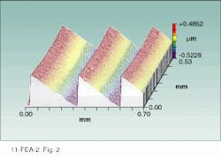
Single-point diamond turning skirts the rounding issues of LPG while avoiding the binary nature of lithographic techniques. At Rochester Photonics Corp. (RPC, Rochester, NY), we have been able to use SPDT to realize the sharp zone boundaries and smooth, continuous blaze surfaces necessary to achieve high diffraction efficiency with proper tool design and process control. DOEs produced by this method exhibit diffraction efficiencies ranging consistently between 97% and 99% at the design wavelength, with measured blaze-surface rms roughnesses of approximately 40 Å. To the best of our knowledge, these are the highest diffraction efficiencies achieved for visible-light DOEs.
Advantages of hybrid lenses
A conventional refractive achromat consists of two different glass types, crown and flint, that bring two wavelengths to a common focal point. The powers of the constitutive crown and flint elements are typically 1.5 to 2.5 times greater than that of the combination, which implies steep surface curvatures and makes it difficult to produce low-f-number achromats.
In essence, a diffractive lens can be used as a replacement for the flint-glass materials in a vast majority of broadband optical systems, for example, allowing designers to achromatize an optical system with only a single type of glass or plastic. Such a hybrid refractive/diffractive lens offers performance as good or better than conventional doublets, while exhibiting all of the advantages of diffractive optics.
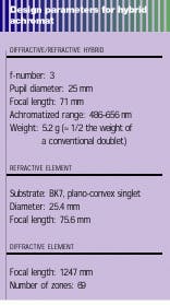
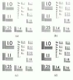
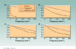
Unlike conventional achromats, the optical power of both the diffractive and refractive lens elements in a hybrid system is positive, reducing the surface curvature of the refractive element and allowing the production of low-f-number achromats. In addition, the weight of a hybrid achromat is typically only one-half to one-third that of the corresponding conventional achromat. Because one can eliminate expensive and difficult-to-work flint-type materials from the system and use only a single, low-cost, crown-type glass for the refractive portion of the lens, hybrid lenses offer significant cost savings. Also, the diffractive lens can be fabricated directly onto the surface of the refractive element, simplifying mounting and assembly requirements and providing additional cost savings.Comparison of the MTFs for the hybrid lens and the conventional doublet reveals that the achromat incorporating the DOE offers improved performance over a broad range of spatial frequencies. The MTF of the high-diffraction-efficiency lens drops to 0.5 at approximately 125 mm-1, whereas that of the conventional achromat lens drops to 0.5 at 75 mm-1.
High-efficiency hybrid diffractive/ refractive systems offer advantages in a wide variety of applications including visible-wavelength optical systems, laser systems, infrared imaging and sensors, head-mounted displays, and micro-optics. Hybrid systems achieve better performance at lower cost than conventional refractive designs, often providing solutions that cannot be achieved with conventional systems. Given the recent breakthroughs in performance, the future for diffractive optics technology is indeed bright.
ACKNOWLEDGMENTS
Special thanks to Robert Michaels and Steven Mack at Rochester Photonics for assistance with the laboratory measurements.
