ADAPTIVE OPTICS: Wavefront correction finds use in bioimaging applications
ALEX CABLE, SCOTT BARRY, AND LORI HOWE
The field of optomechatronics continues to rapidly expand as designers of optical systems increasingly incorporate active components, including transducers and sensors, active and adaptive optical elements, and real-time microprocessor control. Such highly dynamic optical instruments offer performance and application potential far beyond even the theoretical limits of instruments consisting only of static optical elements.
In the case of adaptive optics, astronomy has offered a primary motive for development since 1953, when Horace Babcock suggested active optical compensation to address inherent challenges of imaging through the atmosphere.1 Turbulence among layers of air with different densities generates dynamic refractive-index gradients and time-dependent changes in the optical path length of incident light. If no correction is applied, resulting amplitude and phase distortions in the electromagnetic wavefront produce shimmering bright or dark regions in the resulting image, severely limiting angular resolution of ground-based telescopes. Though Babcock’s suggested method of using a layer of oil on a mirror with an electrostatically charged surface to change the local oil thickness was never implemented, his basic design concept is still used today in many adaptive-optics applications. Deformable mirrors with computer-controlled surface profiles are now commonly used to correct wavefront distortions caused by atmospheric turbulence.
Early developments in adaptive optics were funded by the defense industry during the 1960s, but by the 1980s, adaptive optics had gained a foothold in astronomy for improving the performance of ground-based telescopes. The basic design included real-time measurements of the wavefront using a wavefront sensor (Shack-Hartmann or variable-shear interferometer) combined with a wavefront corrector (deformable mirror or liquid-crystal spatial light modulator). As with many other technologies, once developed, adaptive optics has been extended to other applications.
Adaptive scanning optical microscope
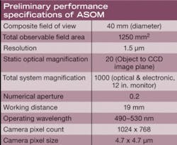
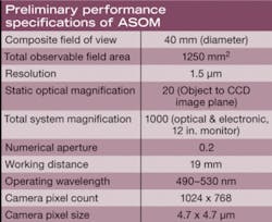
In 2005 Ben Potsaid, John Wen, and Yves Bellouard at the Center for Automation Technologies and Systems (CATS) of Rensselear Polytechnic Institute (RPI; Troy, NY), developed an adaptive scanning optical microscope (ASOM) based on a MEMS deformable mirror that corrects for off-axis wavefront aberrations in the objective lens. This new microscope design, when combined with a high-speed post-objective scanning mirror, a spatial light modulator, and a scan lens, produces images with micron-level resolution and a large effective field of view, thus offering a relatively economical approach to imaging performance traditionally obtained only in very high-resolution microscopes. In a subsequent ASOM design implemented by a Thorlabs/RPI team, the total composite field of view exceeds 1250 mm2 with a 1.5 µm resolution (see table).
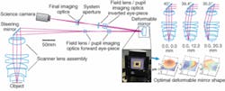
A telecentric scan lens in the ASOM system was designed for finite conjugate imaging with a 40 mm field of view (see Fig. 1). It has a 19 mm back focal length, operates at 0.20 NA, and comprises seven optical elements. A custom-designed 75 mm fast MEMS steering mirror provides 140 electrostatic actuators distributed across a 3.3-mm-square aperture. The CCD science camera has 1024 × 768 pixels on a 4.7 µm pitch.
In a traditional microscope, the field of view, limited by the objective lens, is relatively small. To image large samples at high resolution, the objective must be scanned across the sample (either by moving the microscope or the sample). The scanning mechanism in the ASOM, however, is a low-mass, high-speed steering mirror that scans the field of view through an objective lens.
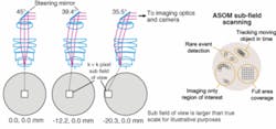
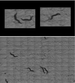
In this configuration, off-axis light experiences significant wavefront distortions from the objective lens that would normally cause image blurring, but by using a deformable mirror with real-time control, the system compensates for wavefront distortions to yield diffraction-limited imaging with uniform resolution. Scanning across the sample allows an image mosaic to be constructed that provides the enhanced field of view. This could prove useful in biological applications, for instance, in which it is often desirable to get cellular-level resolution (approximately 1 µm), while still maintaining a large field of view to monitor gross anatomical information at a centimeter scale, or to observe living organisms that might otherwise “swim” out of the viewing field (see Fig. 2).
Living specimens
The fast scanning mirror in the ASOM circumvents the traditional scanning stages used in many microscope applications. By eliminating the need to move the sample, ASOM technology enables the imaging of live specimens while incorporating fixed sensors or manipulators within the test environment. It also eliminates mechanical stage movements that limit scanning speeds and introduce disruptive vibrations in the liquid or viscous media used with many living samples.2 With tile-to-tile movement times under 5 ms, our ASOM design can move up to 100 times faster than a mechanical microscope stage, and frame rates of up to 100 frames per second on a composite image are possible with high-speed CCD cameras. Potential high-scan-rate applications include drug discovery and high-throughput screening.
Beyond biology, potential applications include micromanufacturing. Imaging is becoming an increasingly important part of the industry with noncontact inspection and robotic manipulation being essential in certain production environments. For micromanufacturing, ASOM technology would enable high-magnification examination of select areas while also viewing an entire workspace, potentially facilitating an overall assembly process by simultaneously monitoring multiple robotic systems operating in parallel. Rensselaer previously demonstrated automatic tracking of two microgrippers by the ASOM using real-time vision-processing algorithms (see Fig. 4).3 While the microgrippers moved independently in the workspace, two image tiles followed the first gripper and two additional image tiles followed the second gripper, to aid in manipulating parts and avoiding collisions.
ACKNOWLEDGMENTS
The authors would like to acknowledge Edward Kibblewhite, one of the pioneers in adaptive optics and a University of Chicago professor of astronomy and astrophysics, for the inspiration that led to this collaboration between RPI and Thorlabs.
REFERENCES
1. H.W. Babcock, Publications of the Astronomical Society of the Pacific 65(386) 229 (October 1953).
2. B. Potsaid et al., Optics Express 13(17) 6504 (Aug. 22, 2005)
3. B. Potsaid et al., Proc. IEEE Int’l. Conf. Robotics and Automation (ICRA) 1024 (2006).
ALEX CABLE is founder and CEO, SCOTT BARRY is the ASOM business unit leader, and LORI HOWE is on the marketing staff at Thorlabs, 435 Route 206, Newton, NJ 07860; e-mail: [email protected]; www.thorlabs.com.
